background image

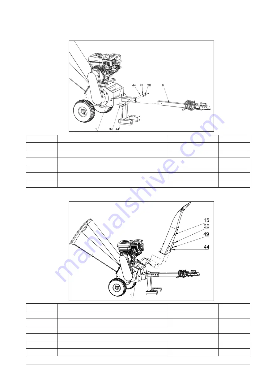
5. Installation tow bar

Parts no.

Description

Specifications

Quantity

1

Machine body assembly

1

6

Tow bar

1

20

Lock nut

M10

2

37

Bolt

M10x65

2

44

Washer

M10

4

49

Spring washer

M10

2

6. Installation discharge chute assembly

Parts no.

Description

Specifications

Quantity

1

Machine body assembly

1

15

Discharge chute assembly

1

30

Bolt

M10x30

4

44

Washer

M10

4

49

Spring washer

M10

2

71

Discharge to frame rubber

1

W W W . T M G I N D U S T R I A L . C O M

P 1 3 / 2 3

T o l l F r e e : 1 - 8 7 7 - 7 6 1 - 2 8 1 9

Summary of Contents for TMG-GWC5

Page 1: ...ead the product manual completely before assembly Check against the parts list to make sure all parts are received Wear proper safety goggles or other protective gears while in assembly Missing parts...

Page 2: ...ould result in minor or moderate injury NOTICE This information is important in proper using of your machine Failure to follow this instruction could result in damage to your machine or property Addit...

Page 3: ...PART I General Safety Rules Safety Labels Found on Your Unit A A B C D E W W W T M G I N D U S T R I A L C O M P 0 3 2 3 T o l l F r e e 1 8 7 7 7 6 1 2 8 1 9...

Page 4: ...structions manual before you use the Wood Chipper Become familiar with the operation and service recommendations to ensure the best performance of your machine W W W T M G I N D U S T R I A L C O M P...

Page 5: ...n using the wood chipper NOTICE A Always feed from the side B It is better to have a second trained operator within easy reach of the machine C Maintain strict discipline at all times and service mach...

Page 6: ...low children to operate the Wood Chipper Safety with Gasoline Powered Machines WARNING Gasoline is a highly flammable liquid Gasoline also gives off flammable vapor that can be easily ignited and caus...

Page 7: ...Exercise caution to avoid slipping or falling D See manufacturer s instructions for proper operation and installation of accessories E Never use the machine without ensuring that all guards and shiel...

Page 8: ...d keep the equipment in good operating condition A Note to All Users List of warnings and cautions cannot be all inclusive If situations occur that are not covered by this manual the operator must app...

Page 9: ...SPECIFICATIONS Start Recoil Start Engine 13 5HP four strokes Power Gasoline Chipper Capacity 4CBM hour to 6CBM hour Wood Diameter diameter 120mm Permitted wood width 310mm Chipper Blade twin reversib...

Page 10: ...Description Quantity No Description Quantity 1 Machine body assembly 1 6 Tow bar 1 3 Feet fixation 1 11 In feed assembly 1 4 Standing leg 1 15 Discharge chute assembly 1 5 Tire 2 80 Tool wrench 2 W W...

Page 11: ...fications Quantity 1 Machine body assembly 1 11 In feed assembly 1 35 Bolt M8x20 2 42 Washer M8 2 47 Spring washer M8 1 66 Feed to frame rubber 1 3 Installation tire system W W W T M G I N D U S T R I...

Page 12: ...r M30 4 51 Split pin 4x32 2 74 Rubber cover 2 4 Installation standing leg assembly Parts no Description Specifications Quantity 1 Machine body assembly 1 3 Feet fixation 1 4 Standing leg 1 21 Lock nut...

Page 13: ...her M10 4 49 Spring washer M10 2 6 Installation discharge chute assembly Parts no Description Specifications Quantity 1 Machine body assembly 1 15 Discharge chute assembly 1 30 Bolt M10x30 4 44 Washer...

Page 14: ...electric wire find the contact join Step 3 Contact and A electric wire Contact and B 1 electric wire Contact and B 2 electric wire B 2 Emergency Stop Switch A B Protection Switch B 1 1 3 2 3 A B 1 2...

Page 15: ...and incorrect methods of Chipping woods Never using an incorrect or unsafe method Starting 1 Position your Wood Chipper on flat dry ground and then stop the front wheel with brake make sure the machin...

Page 16: ...en loading This is a very UNSAFE method and could result in injury to your hands Do not reach or step across the rail while the Wood Chipper is running This is a very UNSAFE method which could cause p...

Page 17: ...egular Maintenance Checklist Procedure Before Each Use Every 3 Hours Every 25 Hours Every 100 Hours Check engine oil level Check general equipment condition Check wedge for sharpness Grease surface of...

Page 18: ...he direction without immediate replacement Turn the roller axle with wrench 1 Loosen the screws with T wrench when you see the blade 2 Replace with a new blade 3 After changing the blade adjust the lo...

Page 19: ...27 screw Move 59 on U groove observe that the spacing between the roller blade and the lower blade spacer is within 1 3mm Lock screw 27 Finally lock screw 16 Adjust blade clearance 1 3mm then lock sc...

Page 20: ...Run position Is the air filter clean If it s dirty change it following the procedure in the engine manufacturer s owner s manual Is the spark plug clean If it s fouled or cracked change it If it s oi...

Page 21: ...djust or replace belts as needed Operator Lever not engaging rack with pinion gear Clean wood chips or other debris from under rack Clean accumulated dirt from frame where carriage assembly rests agai...

Page 22: ...Parts Diagrams W W W T M G I N D U S T R I A L C O M P 2 2 2 3 T o l l F r e e 1 8 7 7 7 6 1 2 8 1 9...

Page 23: ...t M8 11 58 Lower blade 1 19 Lock nut M12 10 59 Return blocking plate 1 20 Lock nut M10 14 60 Roller pulley 1 21 Lock nut M10 3 61 Rubber pad 2 22 Slotted nut 2 62 Tow hitch 1 23 Nut M12 6 63 Engine fi...

Reviews: