
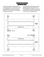


Fig 14.4
NOTE:
There will be initial stretching of the cables in the
beginning and/or with increased loads. Adjust the
Cables as outlined above a week after first use, then
every three to six months thereafter depending on
usage and/or to compensate for stretch.
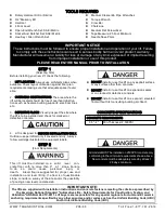
8. Press the safety lock release handle and HOLD, and
check that all Safety Locks are functioning
properly.Lower the lift by pressing the power unit
lowering valve simultaneously.
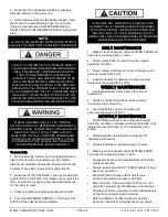
KEEP HANDS AND FEET CLEAR. Remove hands and
feet from any moving parts. Keep feet clear of lift when
lowering. Avoid pinch points
9. Check all MAIN SAFETY LOCKS to make sure
they move freely and spring back to the lock position
when released. Lubricate all SAFETY PIVOT points
with
WD-40 or equal.
10. Run the lift up and down a few times to
ensure that the Locks are engaging uniformly and
that the safety release mechanisms are
functioning. Re-adjust if necessary
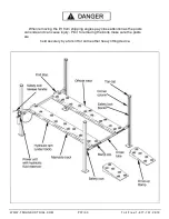
STEP 14
(Anchoring The Columns)
IMPORTANT NOTE:
The lifts are supplied with installation instructions
and concrete fasteners meeting the criteria as
prescribed by the American National Standard
"Automotive Lifts - Safety Requirements for
Construction, Testing, and Validation" ANSI/ALI
ALCTV-2011. Lift buyers are responsible for any
special regional structural and/or seismic anchoring
requirements specified by any other agencies and/or
codes such as the Uniform Building Code (UBC)
and/or International Building Code (IBC).
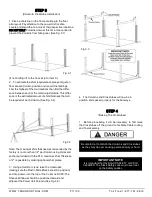
1.
Before proceeding, double check the
measurements and make certain that the bases of
each Column are square and aligned with the chalk
line. Raise the lift up and down and make sure it
operates properly at the locations prescribed by the
markings on the floor.
(See Fig. 14.1)
Fig. 14.1
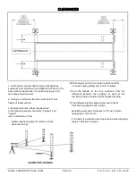
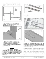
2.
Using the Base plate on each Column as a guide,
drill each anchor hole approximately 4-1/2” deep using
a rotary hammer drill and 3/4” concrete bit.
(See Fig. 14.2)
Fig. 14.2
3.
After drilling, remove dust thoroughly from each
hole using compressed air and/or bristle brush. Make
certain that the Columns remain aligned with the chalk
line.
ALWAYS WEAR SAFETY GOGGLES
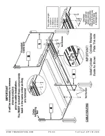
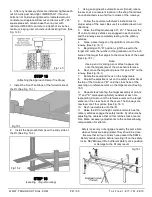
4.
Assemble the Washers and Nuts on the anchors
then tap each hole with a hammer until the washer rests
against base plate. Be sure that if shimming is required,
enough threads are left exposed. (See Fig. 14.3)
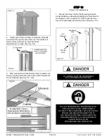
5.
If shimming is required, insert the shims as necessary
the base plate so that when the anchor bolts are tight-
ened, the columns will be plumb. (See Fig. 14.4)
Fig 14.3
WWW.TMGINDUSTRIAL.COM
P20/33
Toll Free:1-877-761-2819
Noted: the shims
not include


