


Chapter 4 Hardware Settings
TI5VGA Socket 7 MVP3 ATX Motherboard User’s Manual
19
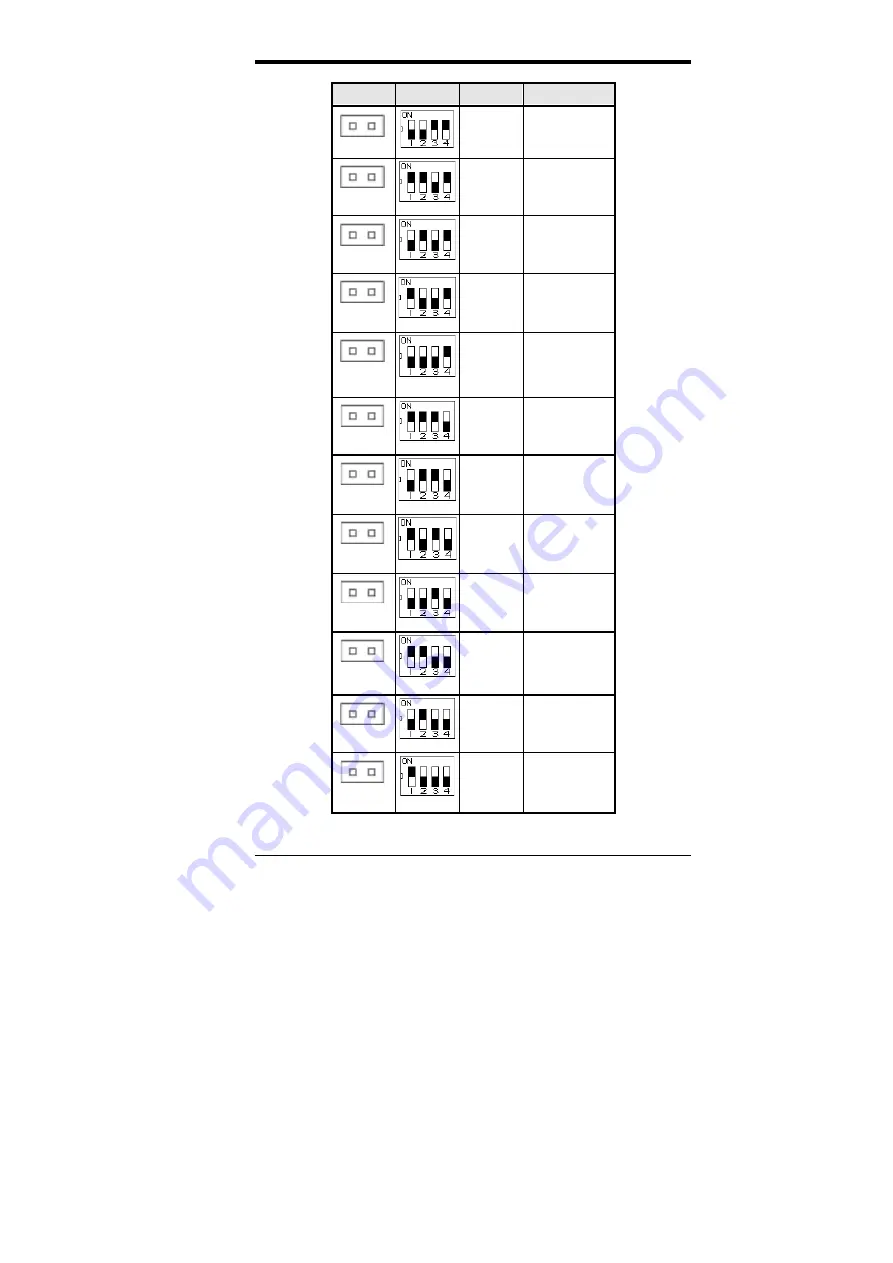
JP3
SW2
V
CORE
CPU
open
off off on on
3.2V
K6-233
(0.35
µ
)*
open
on on off on
3.1V
open
off on off on
3.0V
open
on off off on
2.9V
K6-166/200
6x86MX
open
off off off on
2.8V
WinChip 2-3D
(0.35
µ
)*
P55C
6x86L
open
on on on off
2.7V
open
off on on off
2.6V
open
on off on off
2.5V
open
off off on off
2.4V
K6-3/400/450
K6-2/400/450
open
on on off off
2.3V
open
off on off off
2.2V
K6, K6-2/500
(0.25
µ
)*
open
on off off off
2.1V
* 0.25
µ
and 0.35
µ
refer to manufacturing processes.


