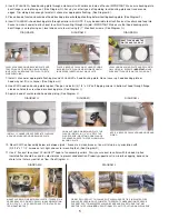
4. Insert X
CHANGE
R
TM
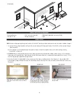
hood backing plate through exterior wall with collars on inside of house. IMPORTANT: Make sure backing plate
bent flange is on top facing out, (See Diagram G). For vinyl or other types of lap siding, level backing plate and trace around
edges. Trim siding back enough to install J channel or appropriate flashing, (See Diagram E).
5. Place a bead of caulk on back side of hood backing plate or building sheathing before inserting backing plate, (See Diagram F).
6. Insert X
CHANGE
R
TM
hood backing plate through exterior wall. NOTE: It may be desirable to attach flex duct to collars and feed into
house to make it easier to attach duct to collars if mounting through rim joist. IMPORTANT: Make sure that hood backing plate
bent flange is on top facing out, level and secure to wall using (4) 1” sheetrock screws, (See Diagram G).
7. Install J channel or appropriate flashing around X
CHANGE
R
TM
hood backing plate. Do not cover up hood backing plate or
hood may not fit in J channel, (See Diagram H).
8. Hook X2R hood on backing plate top bent flange, and install (4) 1/4” x 3/8” self tapping screws in bottom of hood through flange
clearance holes to screw hood into backing plate, (See Diagram I).
9. Apply a bead of caulk around hood and siding, (See Diagram J).
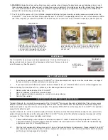
10. Mount X2R Fan Assembly below or between joists / trusses to a cross brace or to a wall stud in any orientation with
(3) 5/16” x 1 1/4” screws on left, right and center mounting feet, (See Diagram K).
11. Use 6” flex duct to connect X
CHANGE
R
TM
hood to fan assembly collars. Firmly secure duct to collars with included zip ties.
Insulated flex should be used in cold climates to prevent condensation. Properly support duct to minimize sagging, bends and
sharp turns that may restrict air flow, (See Diagram L).
5
DIAGRAM E
DIAGRAM F
LEVEL XCHANGER HOOD BACKING PLATE AND
TRACE FLANGE. TRIM SIDING BACK SO BACK-
ING PLATE CAN BE MOUNTED FLUSH TO EXTE-
RIOR SHEATHING.
PLACE A BEAD OF CAULK ON XCHANGER HOOD
BACKING PLATE FLANGE OR BUILDING SHEATH-
ING BEFORE INSERTING BACKING PLATE.
DIAGRAM H
INSTALL J CHANNEL OR APPROPRIATE FLASHING
AROUND XCHANGER HOOD BACKING PLATE.
DIAGRAM K
MOUNT X2R BELOW OR BETWEEN JOISTS / TRUSSES TO A
CROSS BRACE OR ON A STUD WALL IN ANY ORIENTATION.
USE (3) 5/16” X 1 1/4” SCREWS ON LEFT, RIGHT AND CEN-
TER MOUNTING FEET.
DIAGRAM L
FIRMLY SECURE DUCT TO COLLARS WITH INCLUDED ZIP TIES. INSULATED FLEX
SHOULD BE USED IN COLD CLIMATES TO PREVENT CONDENSATION. PROPERLY
SUPPORT DUCT TO MINIMIZE SAGGING, BENDS AND SHARP TURNS THAT MAY
RESTRICT AIR FLOW.
NOTE:
USE OPTIONAL DT2-6 KIT IF DUCTING ON DISCHARGE.
DIAGRAM J
APPLY A BEAD OF CAULK AROUND HOOD AND
SIDING..
DIAGRAM G
LEVEL HOOD BACKING PLATE AND SECURE TO
WALL USING (4) SCREWS.
IMPORTANT:
MAKE
SURE BENT FLANGE IS ON TOP FACING OUT.
DIAGRAM I
HOOK X2R HOOD ON BACKING PLATE TOP
FLANGE. INSTALL (4) 1/4” X 3/8” SELF TAP-
PING SCREWS IN BOTTOM HOOD FLANGE
CLEARANCE HOLES TO SCREW HOOD INTO
BACKING PLATE.
BENT FLANGE MUST BE
ON TOP AND FACE OUT


