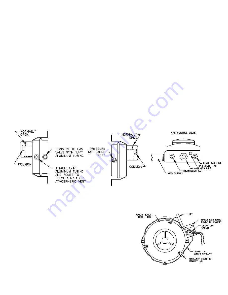
GAS PRESSURE SWITCH INSTALLATION
Remove the gas pressure switch from the carton also remove the 1/8” compression fitting, the four 1/2” x #10 self tapping screws and
the 2 sections of 1/4” diameter aluminum tubing from the
master carton liner.
The gas pressure switch is mounted on the casing of the water heater adjacent to the heater’s thermostat/valve. It should be mounted
close enough so that the supplied 1/4” tubing will reach from the gas pressure switch fittings to the burner. The four provided screws
are self tapping and drilling. They do not require the use of a drill. Their 1/2” length assures that the inner tank will not be penetrated.
1. Mount the gas pressure switch by securing it to the heater casing with a screw in each of the four mounting holes.
2. Using a tube cutter, cut the appropriate length of 1/4” tubing to reach from the fitting marked “connect to gas valve” to the pressure
tap port of the thermostat/valve, (See Diagram B).
NOTE: DO NOT alter the heater’s PILOT GAS LINE, (See Diagram B, Gas
Control Valve).
3. Remove the pressure tap plug from the underside of the thermostat/valve and install the supplied compression fitting. Use thread
sealant, do not over tighten.
4. Use 1/4” tubing to connect the fitting installed in step #3 to the fitting marked “connect to gas valve” on the gas pressure switch.
Make sure each end of the tubing is not pinched closed.
5. Measure and cut an appropriate length of tubing to reach from the fitting marked “warning” to the burner of the water
heater. Connect tubing to gas pressure switch and route to pilot/burner area.
NOTE: DO NOT locate the tubing in the
pilot/burner flame.
6. Conduct a gas leakage test of the aluminum tubing as outlined in the 1988 (or latest) edition of NFPA 54, ANSI Z223.1, part 4.
NOTE:
The gas pressure switch has a built in pressure tap marked “gauge port”.
LINEAR LIMIT SPILLAGE SENSING SWITCH INSTALLATION
PURPOSE:
To provide a means for appliance shut-down in the event of flue blockage
or Power Venter failure.
OPERATION:
When concentrated spillage of the products of combustion occurs from the
draft hood, the linear limit sensing switch circuit will open preventing burner
operation.
1. Attach the linear limit sensing switch mounting bracket to the top of the
water heater using the sheet metal screws provided. The linear limit
bracket should be approximately 1/2” from the draft hood.
2. Attach the three linear limit capillary mounting brackets around the draft
hood, equally spaced.
3. Insert the linear limit spillage sensing switch capillary into the “U” of the
linear limit brackets outlining the perimeter of the draft hood. The linear limit capillary may be overlapped if necessary,
(See Diagram C).
IMPORTANT: DO NOT CUT THE CAPILLARY
, it will be destroyed and water heater will be disabled.
4
DIAGRAM B
DIAGRAM C
NOTE:
Do not alter pilot gas line


