TJERNLUND SS2G SIDESHOT (DISCONTINUED) 8504075 REV 1 1198 Installation Instructions Manual Download Page 11

10

DRAFT ADJUSTMENT PROCEDURE

The SS2G Vent System will properly vent a wide range of BTU/hr. input capacities.  To compensate for different burner capacities,
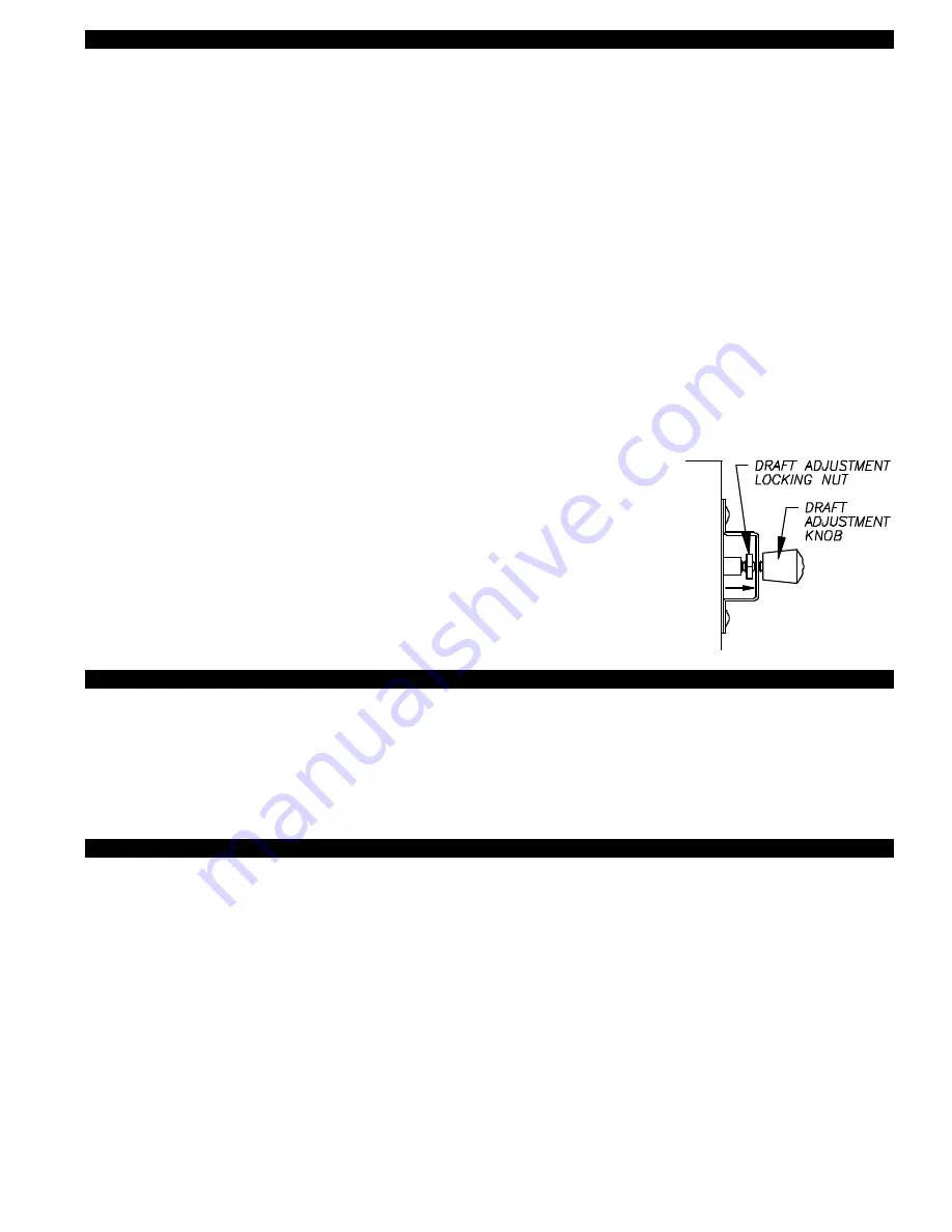
vent connector lengths, types and sizes, it features a draft adjustment located on the back of the venter assembly.  Turning this
draft adjustment knob clockwise will increase draft and raise the BTU capacity.  Turning knob counterclockwise will decrease draft
and lower the BTU capacity.  The SS2G is factory set for the highest draft (BTU capacity).

IMPORTANT:

Before proceeding, close all windows, doors and fireplace dampers.  Turn on all appliances in the structure that exhaust indoor air
such as clothes dryer, exhaust fans, range hoods, bathroom and whole house exhaust fans.  Failure to perform the draft adjust-
ment procedure may cause a poor vent system installation possibly resulting in fire, carbon monoxide poisoning, explosion, per-
sonal injury or property damage.

1.  Place the heating system into operation. NOTE: there will be a slight pause between venter operation and burner operation. If 

installation uses a barometric draft control adjust it to the minimum or least draft setting. Allow heater to operate for 5 minutes.

2. 

PREFERRED METHOD:

MUST HAVE DRAFT GAUGE AVAILABLE

Sample draft one foot after draft hood, diverter or barometric draft control using a draft gauge. If the draft reading is in excess of
-0.05” W.C. turn the draft adjustment knob on the SS2G counterclockwise so that a draft reading of -0.02” to -0.05” W.C. is 
obtained. Never adjust draft to a setting of less than -0.02” W.C. If the vent system is terminated on a wall subject to prevailing 
winds a -0.05” W.C. draft setting is recommended.

3. If a draft gauge is not available test for spillage at the draft hood, diverter or barometric draft control using the flame from a 

match, lighter or candle and determine the following:

A. The flame or smoke is being drawn into the draft hood, diverter or barometric draft control.

B. The main burner is burning properly, i.e. no floating, lifting or flash back.

C. If the heater has a two stage or modulating gas valve verify that burner operates properly at 

both low and high fire.

If the draft appears excessive turn the draft adjustment knob counterclockwise and repeat 
steps A through C.

4. Lock the draft adjustment knob in place by tightening the locking nut behind the bracket, 

(See Diagram K).

5. Turn off appliances and exhaust fans activated for draft adjustment procedure.

DIAGRAM K

COMBUSTION AIR

Adequate combustion air is vital for proper combustion and for safe venting.  Likewise, for proper SS2G performance, adequate
combustion air must be available to the appliance.  Many installers assume adequate combustion air is present, especially in older
homes.  In some cases this is a false assumption, because many older homes have been made "tight" due to weatherization.  Size
the combustion air opening(s) into the appliance room as outlined NFPA 54/NFPA 211.  When installing a SS2G, it is not neces-
sary to supply any more combustion air than normally required when conventional venting.  Common symptoms of inadequate
combustion air include: Fan Proving Switch short cycling, odor present at the end of burner cycle, outside air enters the structure
through the SS2G Vent System on SS2G/Appliance off cycle.

FINAL SYSTEM OPERATION CHECK-OUT

1. Adjust thermostat or appliance controls to call for heat.

2. Verify that the SS2G operates first, prior to burner ignition.

Allow heating equipment and SS2G to operate continuously while performing steps 3-5.

3. Close all doors and windows of the building.  If heating equipment is installed in utility room or closet, close the entrance door to

this room.  Close fireplace dampers.

4. Turn on all appliances in the structure that exhaust indoor air during their operation, e.g. turn on clothes dryer and exhaust fans 

such as range hoods, bathroom exhaust and whole house fans.

5. Allow SS2G and equipment to operate for at least 15 minutes. Tripping of the burner circuit by the Fan Prover Switch during the

15 minute operation indicates an unsafe operating condition. Turn fuel supply off to appliance and DO NOT OPERATE 
UNTIL UNSAFE VENTING CONDITION IS INVESTIGATED BY QUALIFIED SERVICE PERSONNEL.

6. Turn thermostat or equipment controls to the "off" position. Verify that the post-purge timer operates the SS2G for approximately

45 seconds while burner is not firing before the SS2G turns off. 

7. Return all windows, doors and exhaust fans to their original conditions of use.

Summary of Contents for SS2G SIDESHOT (DISCONTINUED) 8504075 REV 1 1198

Page 1: ... INSTRUCTIONS THOROUGHLY BEFORE ATTEMPTING INSTALLA TION OR OPERATION FAILURE TO FOLLOW THESE INSTRUCTIONS MAY RESULT IN IMPROPER INSTALLATION ADJUSTMENT SERVICE OR MAINTENANCE POSSIBLY RESULTING IN FIRE ELECTRICAL SHOCK CARBON MONOXIDE POISONING EXPLO SION PERSONAL INJURY OR PROPERTY DAMAGE DO NOT DESTROY PLEASE READ CAREFULLY AND KEEP IN A SAFE PLACE FOR FUTURE REFERENCE MODEL SS2G INSTALLATION ...

Page 2: ...s heating equipment It is factory assem bled and wired The SS2G automatically vents the flue gases from heating equipment to the outdoors By recirculating indoor air with a cooling fan surrounding combustible materials remain at safe temperatures After each burner cycle the SS2G will continue to operate for a nonadjustable timed period of approximately 45 seconds to purge the heater and vent of re...

Page 3: ... through the Fan Proving Switch must not exceed its nameplate ratings 5 Vent runs of over 15 linear feet require the use of an approved insulated vent connector to prevent problems related to condensation CAUTIONS The Power Venter must be installed by a qualified installer in accordance with these instructions and all local codes or in their absence in accordance with the latest edition of The Nat...

Page 4: ...hould be recognized that generalized proce dures cannot anticipate all situations Accordingly in some cases deviation from this procedure may be necessary to determine safe operation of the equipment a Perform this procedure prior to any attempt at modifications of the appliance or installation of the SS2G b If it is determined there is a condition which could result in unsafe operation shut off t...

Page 5: ...jeopardize people overheat combustible structures or enter buildings Not to be less than 10 feet from an adjacent building The SS2G is also Listed to terminate a minimum of 12 inches from soffits decks or adjacent sidewalls It is not recommended for the SS2G to be terminated on a wall that faces the direction of the prevailing winds Backdrafts by severe winds can interrupt equipment operation 4 DI...

Page 6: ...e rectangular opening should be no larger than 10 1 2 in width by 8 1 2 in height See Diagram C 6 Knock out block material exposing rectangular opening through the wall DIAGRAM C INSTALLING SS2G VENT CABINET 1 a Fold SS2G Vent Cabinet template Page 14 along dashed line and attach between the floor joists ensuring that it is snug against the sill plate and centered between the floor joists Follow s...

Page 7: ... isolation Use the prepunched holes on the wall bracket as a template to mark holes to be drilled into the side wall for mounting screws See Diagram H 4 a If installing the bracket into a wood wall drill 2 pilot holes at each point established in step 3 with a 1 8 drill bit approximately 1 deep and install the screws provided to secure the bracket to the wall b If installing the bracket into a mas...

Page 8: ...round inlet pipe from box 2 Align the 4 slots of the inlet pipe to the 3 pins and proving switch sensing tube push pipe up until it bottoms out in the SS2G inlet 3 Turn the inlet collar clockwise to lock in place See Diagram I IMPORTANT After vent pipe is installed verify inlet pipe is locked tightly in place INSTALLATION OF VENT PIPE The SS2G inlet is designed to accept 4 single wall or type B ve...

Page 9: ...is energized Normal combustion sequence for the furnace begins induced draft furnace blower starts its proving switch makes energizing ignition control and or gas valve DO NOT OPERATE THE FURNACE WITHOUT THE FAN PROVING SWITCH WIRED INTO THE 24V FURNACE CIRCUIT NOTE When Power Venter is interlocked with a thermostat wire all zones circulators and limits as would normally be done if venting into a ...

Page 10: ...9 ...

Page 11: ...h fire If the draft appears excessive turn the draft adjustment knob counterclockwise and repeat steps A through C 4 Lock the draft adjustment knob in place by tightening the locking nut behind the bracket See Diagram K 5 Turn off appliances and exhaust fans activated for draft adjustment procedure DIAGRAM K COMBUSTION AIR Adequate combustion air is vital for proper combustion and for safe venting...

Page 12: ...ss W C at thermostat No call for heat Contact Tjernlund Products Inc for additional assistance 24 Volts present Step 1 Confirm that thermostat is not calling for heat Step 2 With the Power Venter running remove the ORANGE wire on Relay Timer terminal 5 Result Power Venter should shut off within approximately 45 seconds Yes 24 Volts not present SYMPTOM 2 POWER VENTER DOES NOT RUN DURING CALL FOR HE...

Page 13: ... to SS2G Check Fan Proving Switch tube for clear passage Step 5 Remove call for heat to SS2G Remove the BLUE and YELLOW wires from SS2G Proving Switch Activate thermostat to call for heat With SS2G running check for continuity across the COM and N O terminals of Fan Proving Switch Result Contacts on switch should be closed Step 7 Reset the SS2G High Limit by depressing the button located on the ce...

Page 14: ...rnlund distributor for replacement Please include SideShot date code component was taken from The date code is located on the Electrical Box coverplate If the date code is older than 30 months you will need to provide a copy of the original installation receipt to your distributor Credit or replacement will only be issued to a Tjernlund distributor after the defective part has been returned prepai...

Reviews: