13
1.2 Front Panel and Rear Panel Illustration
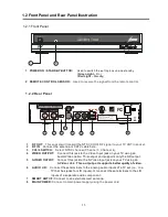
1.2.1 Front Panel
1 POWER ON /
STANDBY BUTTON:
Used to switch the set top box on and standby
(Green Light –
On)
(Red Light –
Standby)
2 REMOTE CONTROL SENSOR:
Used to receive the signal from the remote control.
1.2.2 Rear Panel
1
RF OUT:
This socket will transmit the NTSC CH3/4 RF signal to your TV ANT in socket.
2
RF IN:
Connect the antenna or CATV cable here.
3
CH3/4 SWITCH:
Select NTSC channel (Channel 3, Channel 4).
4
VIDEO OUTPUT:
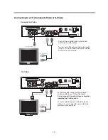
Connect this jack to the Video Input jack on your TV using an
Audio/Video cable. This output port supports only the SD output.
5
S-VIDEO OUTPUT:
Connect this jack to the S-Video Input jack on your TV using an
S-Video
cable.
This output port supports better quality of video
.
6
AUDIO L/R:
Connect these terminals to the analog audio inputs of a TV set (i.e., to a
TV that has jacks for L/R inputs). Or connect these terminals to the L/R
inputs of a separate audio component.
7
SMART ANT I/F:
Connect to an external smart antenna.
8
MAIN POWER:
Connect to main power supply using the power cord.
1
2
6
3
7
1
2
4
5
8
Summary of Contents for STB-T12
Page 1: ...USER MANUAL STB T12...


