
© Titan Tool Inc. All rights reserved.
25
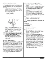
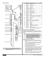
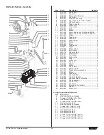
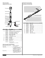
Servicing the PowrTex 6900 SF Fluid Section
IMPORTaNT: use of non-Titan service parts may void
warranty. ask for original parts made by Titan for best
services. This pump should receive a routine servicing
after approximately 1,000 hours of use. Earlier servicing is
required if there is excessive leakage from the top packing
or if pump strokes become faster on one stroke or the other.
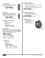
The use of Titan Piston Lube (P/N 314-480) is recommended
as an upper packing lubricant. Do not substitute oil, water, or
solvent for an upper packing lubricant.
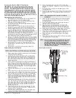
Disassembling the Fluid Section
1. Remove the foot valve housing (22), pump cylinder (15),
and cylinder spacer (14) with a strap wrench.
2. Slide the retaining ring (1) up with a small screwdriver,
then push the connecting pin (2) out.
3. Pull the displacement rod (6) through the lower cavity of
the motor/pump block.
4. Remove the
PTFE
o-ring (3), upper packing spring (5),
and upper packing set (4) from the motor/pump block.
5. Hold the displacement rod (6) in a vise by the flats at the
top of the displacement rod. Remove the outlet valve
housing (13) with a wrench while holding the displacement
rod horizontal with a wooden support, if necessary.
Remove the seal washer (12), outlet valve seat (11), outlet
valve ball (10), outlet valve cage (9), lower packing set (4),
lower packing spring (8), and spring retainer (7).
6. Using a 1/2” extension bar attached to a 1/2” drive ratchet,
insert the end of the extension bar into the square opening
of the foot valve cage (18) inside the foot valve housing
(22). Unscrew and remove the foot valve cage along with
the wave washer (17) from the foot valve housing.
7. Remove the
PTFE
o-ring (3), foot valve ball (19), foot
valve seat (20), and seat o-ring (21) from the foot valve
housing (22).
8. Remove the o-ring (16) from the pump cylinder (15).
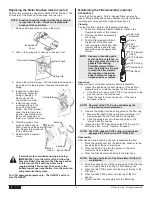
Reassembling the Fluid Section
NOTE: Use
PTFE
tape on all threaded pipe connections.
1. Place a new seat o-ring (21) into the groove in the bottom
of the foot valve housing (22).
2. Inspect the foot valve seat (20) for wear. If one side is
worn, flip the seat to the unused side. If both sides are
worn, install a new seat. Place the new or flipped seat
(worn side down) into the bore at the bottom of the foot
valve housing (22).
3. Place a new foot valve ball (19) onto the foot valve seat
(20). Using a 1/2” extension bar attached to a 1/2” drive
ratchet, insert the end of the extension bar into the square
opening of the foot valve cage (18) and screw the cage
into the foot valve housing (22). Torque the cage to 300
in./lbs. (25 ft./lbs.).
4. Place the wave washer (17) on top of the foot valve cage
(18).
5. Insert a new
PTFE
o-ring (3) into the groove of the foot
valve housing (22). Lubricate the o-ring using oil or grease.
6. After soaking the new leather packings in oil (preferably
linseed oil), reassemble the lower packing set (4). Place
the set onto the outlet valve housing (13) with the peak
of the “V” packings pointing down toward the hex on the
outlet valve housing.
7. Inspect the outlet valve seat (11) for wear. If one side is
worn, flip the seat to the unused side. If both sides are
worn, use a new seat. Insert the outlet valve cage (9),
new outlet valve ball (10), new or flipped seat (worn side
away from ball), and a new seal washer (12) into the
displacement rod (6).
8. Clean the threads on the outlet valve housing (13) and
coat the threads with blue Loctite #242. Make sure the
Loctite is only on the threads.
9. Place the lower packing spring (8) onto the outlet valve
housing (13) followed by the spring retainer (7).
10. Screw the displacement rod (6) and the outlet valve
housing (13) together. Tighten in a vise to 900 in./lbs. (75
ft./lbs.).
11. Insert the
PTFE
o-ring (3) into the upper grove of the
motor/pump block.
12. Insert the upper packing set (4) into the motor/pump block
with the peak of the “V” packings pointing up toward the
motor.
NOTE: The packings must be soaked in oil before
installation.
13. Place the upper packing spring (5) into the motor/pump
block with the small tapered end facing up toward the
motor/pump block.
14. Insert the displacement rod (6) up through the upper
packings in the motor/pump block.
15. Align the holes in the displacement rod (6) and the
hydraulic piston rod and insert the connecting pin (2).
Replace the retaining ring (1) over the connecting pin.
16. Thread the short threads of cylinder spacer (14) into the
motor/pump block and tighten with a strap wrench.
17. Thread the short threads of the pump cylinder (15) into the
cylinder spacer (14) and tighten with a strap wrench.
18. Place the o-ring (16) onto the top grove of the pump
cylinder (15).
19. Thread the foot valve housing (22) onto the pump cylinder
(15), tighten with a strap wrench.
NOTE: It is not necessary to over-tighten the foot valve.
O-ring seals perform sealing function without
excessive tightening. Full thread engagement
is sufficient. The foot valve may be rotated
backward up to 1/2 turn from full engagement for
convenient hose position.
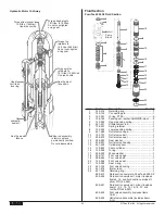
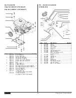
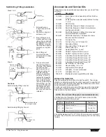
Fluid Section cut-away
Peaks of upper
packings must
face up.
Torque outlet
valve housing
to 75 ft./lbs.
(1095 N/m).
Use blue
Loctite.
Oil cup area
for piston lube
packing
lubricant.
Peaks of lower
packings must
face down.
Lubricate O-ring.


