background image

© Titan Tool Inc.  All rights reserved.

21

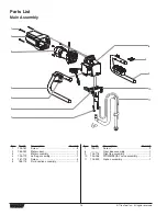
Item

Part #

Description

Quantity

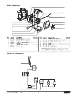
1

700-139

Screw........................................................10

2

704-019

Front cover..................................................1

3

704-173

Crankshaft/gear assembly ..........................1

4

704-174

Thrust washer .............................................1

5

704-176

2nd stage gear............................................1

6

766-101

Pump housing.............................................1

7

700-2060

Connecting rod ...........................................1

8

704-102

Pressure control knob.................................1

9

704-124

Retainer ring ...............................................1

10

704-123

Spring .........................................................1

11

704-158

Plunger .......................................................1

12

704-128

Microswitch .................................................1

13

765-063

Strain relief, 230V .......................................1

14

800-741

Power cord (includes item 13)....................1

Item

Part #

Description

Quantity

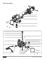
15

704-229

Ground screw .............................................1

16

704-122

Screw..........................................................2

17

766-452

Transducer assembly .................................1

18

800-038

Motor starter ...............................................1

19

704-126

Lock washer................................................2

20

730-260

Screw..........................................................2

21

704-323

Screw..........................................................1

22

704-169

MIcroswitch mounting plate ........................1

23

704-125

Washer........................................................2

24

700-785

Lock washer................................................2

25

704-380

ON/OFF switch ...........................................1

26

704-211

Circuit breaker ............................................1

27

704-363

Capacitor/rectifier kit (includes item 21) .....1

28

766-441

Electrical box cover ....................................1

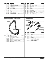
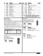
Siphon Assembly (P/N 704-300)

Item

Part #

Description

Quantity

1

700-1023

Siphon tube assembly
(includes items 2–4, and 7) ........................1

2

704-263

Return hose ................................................1

3

700-805

Inlet screen .................................................1

4

704-121

O-ring..........................................................2

704-109

O-ring (for hot solvents, optional)

5

700-1024

Elbow ..........................................................1

6

704-127

Retaining clip ..............................................1

1

2

3

4

5

6

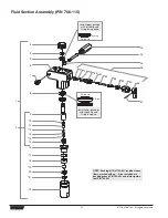
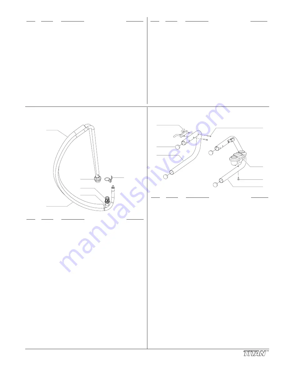
Stand Assembly

Item

Part #

Description

Quantity

1

700-761

Cord wrap ...................................................1

2

710-199

Plug.............................................................4

3

704-164

Leg, left .......................................................1

4

700-642

Screw..........................................................2

5

700-1043

Drip cup ......................................................1

6

704-188

Screw..........................................................1

7

704-156

Leg, right.....................................................1

704-179

Leg, left, complete 
(includes items 1, and 2–4)

704-178

Leg, right, complete
(includes items 2 and 5–7)

1

3

2

4

5

6

7

Summary of Contents for RentSpray 450

Page 1: ...re reading this manual RentSpray 450 Airless Sprayer Owner s Manual For professional use only NOTE This manual contains important warnings and instructions Please read and retain for reference NOTE Th...

Page 2: ...injected directly into the blood stream Consultation with a plastic surgeon or reconstructive hand surgeon may be advisable HAZARD HAZARDOUS VAPORS Paints solvents insecticides and other materials ca...

Page 3: ...s Always unplug cord from outlet before working on equipment Do not use the hose as a strength member to pull or lift the equipment Do not lift by cart handle when loading or unloading Grounding Instr...

Page 4: ...e gun and one on the hose tighten securely Make sure all airless hoses and spray guns are electrically grounded and rated at or above the maximum operating pressure range of the airless sprayer 4 Make...

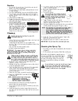
Page 5: ...at the spray gun does not have a tip or tip guard installed NOTE Hold the return hose in the waste container when moving the PRIME SPRAY valve to PRIME in case the sprayer is pressurized NOTE Incompat...

Page 6: ...be applied without runs or sags Holding the gun closer to the surface deposits more paint on the surface and produces a narrower spray pattern Holding the gun farther from the surface produces a thinn...

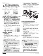
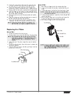
Page 7: ...o a metal waste container 5 Move the PRIME SPRAY valve down to its PRIME position 6 Set the pressure to minimum by turning the pressure control knob fully counterclockwise 7 Turn on the sprayer by mov...

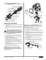
Page 8: ...NOTE Rotate the motor fan manually until the armature gear engages with the mating gear in the pump housing NOTE If the motor will not dislodge from the pump housing Remove the front cover plate Using...

Page 9: ...the hole in the pump block during reassembly Improper alignment may cause damage to the transducer o ring Front Cover Pump Housing Front Cover Screw 2nd Stage Gear Thrust Washer Motor Gear and Crank...

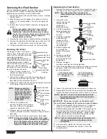
Page 10: ...ump This will prevent the piston rod from rotating during disassembly of the outlet valve Outlet Valve Retainer Outlet Valve Seat Outlet Valve Ball Outlet Cage Crush Washer Piston Rod Foot Valve Housi...

Page 11: ...the new or cleaned filter into the pump block 5 Slide the filter housing over the filter and thread it into the pump block until secure Pump Block Seal Filter Filter Housing NOTE Left handed threads r...

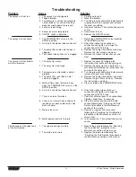
Page 12: ...wing the Servicing the Fluid Section procedure in the Maintenance section of this manual 10 Take sprayer to a Titan authorized service center 1 Repack the pump following the Servicing the Fluid Sectio...

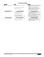
Page 13: ...ith a minimum of 50 x 1 4 grounded textile braid airless paint spray hose 2 Replace the spray tip following the instructions that came with the spray gun 3 Rotate the pressure control knob countercloc...

Page 14: ...n ou un sp cialiste en chirurgie reconstructive de la main DANGER MANATIONS DANGEREUSES Certains produits peintures solvants insecticides ou autres peuvent tre nocifs s ils sont inhal s ou entrent en...

Page 15: ...ents Porter des v tements aptes prot ger la peau et les cheveux du produit utilis Ne pas utiliser le pistolet ou ne pas pulv riser de produits en pr sence d enfants proximit loigner les enfants de l q...

Page 16: ...tos revestimientos inyectados directamente en la corriente sangu nea Puede ser aconsejable consultar con un cirujano pl stico o un cirujano especialista en reconstrucci n de las manos PELIGRO VAPORES...

Page 17: ...del equipo en todo momento No se asome ni se pare sobre soportes inestables Mantenga siempre la posici n firme y el equilibrio efectivos Use la presi n m s baja posible para enjuagar el equipo Mant n...

Page 18: ...ty 1 704 181 Screw 4 2 766 232 Motor cover 1 3 Motor assembly 1 4 704 179 Left leg assembly 1 5 761 178 Screw 4 6 766 115 Fluid section assembly 1 Item Part Description Quantity 7 704 117 Screw 2 8 Ge...

Page 19: ...2 6 704 322 Shroud screw 2 Item Part Description Quantity 7 704 277 Motor 120V complete includes items 1 5 6 10 and 11 1 8 704 258 Y adapter positive red 1 9 704 331 Gasket 1 10 704 250 Motor fan 1 11...

Page 20: ...20 Titan Tool Inc All rights reserved Gear Box Assembly 2 1 10 11 8 9 13 12 14 15 17 16 18 19 20 21 3 24 1 26 27 1 28 25 22 23 4 5 6 7...

Page 21: ...21 704 323 Screw 1 22 704 169 MIcroswitch mounting plate 1 23 704 125 Washer 2 24 700 785 Lock washer 2 25 704 380 ON OFF switch 1 26 704 211 Circuit breaker 1 27 704 363 Capacitor rectifier kit inclu...

Page 22: ...24 23 27 28 29 30 31 32 33 34 35 36 Install lower packings with raised lip and O ring facing up Install upper packing with raised lip and O ring facing down O Ring O Ring Raised Lip Raised Lip NOTE P...

Page 23: ...fan width required for a specific job and by the orifice size that will supply the desired amount of fluid and accomplish proper atomization For light viscosity fluids smaller orifice tips generally a...

Page 24: ...s not apply in the case of damage or wear caused by abrasion corrosion or misuse negligence accident faulty installation substitution of non Titan component parts or tampering with the unit in a manne...

Reviews: