24
repairs at the unit
Impact 540
11.4
replAcINg The moTor
i
The following procedure must only be performed
by a Titan Authorized Service Center.
1. Open the relief valve, valve position PRIME (
k
circulation). Switch the unit OFF. Unplug the power plug
from the outlet.
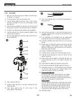
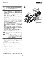
2. Loosen and remove the two motor cover screws (fig. 16,
item 1). Remove the motor cover (2).
3. Loosen and remove the three belly pan screws (3). Remove
the belly pan (4).
4. On the back of the motor, disconnect the wire coming
from the potentiometer and the wire coming from the
transducer. Also, disconnect the two wires coming from
the control panel board (refer to the electrical schematic
in the Parts List section of this manual).
5. Remove the four control panel mounting screws (5). Pull
back the control panel (6) for access to the control panel
board.
6. At the the control panel board, disconnect the two wires
coming from the motor (refer to the electrical schematic in
the Parts List section of this manual).
7. Loosen and remove the four motor mounting screws (7).
8. Pull the motor (8) out of the pump housing.
i
If the motor will not dislodge from the pump
housing:
•
Remove the front cover plate.
•
Using a rubber mallet, carefully tap on the
front of the motor crankshaft that extends
through the slider assembly.
9. With the motor removed, inspect the gears in the pump
housing for damage or excessive wear. Replace the gears,
if necessary.
10. Install the new motor (8) into the pump housing.
11. Secure the motor with the four motor mounting screws
(7).
12. Reconnect the wires (refer to the electrical schematic in
the Parts List section of this manual).
13. Position the control panel (6) on the pump housing and
secure in position using the four control panel mounting
screws (5).
14. Replace the belly pan (4). Secure with the three belly pan
screws (3).
15. Slide the motor cover (2) over the motor. Secure the
motor cover with the two motor cover screws (1).
8
7
1
4
3
2
6
5

