


English
English
© Titan Tool Inc. All rights reserved.
9
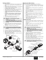
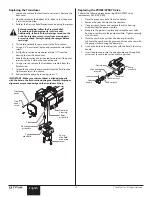
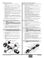
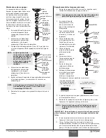
Replacing the Motor
1. Perform the Pressure Relief Procedure and unplug the sprayer.
2. Remove the four motor cover screws. Remove the motor
cover.
3. Remove the four heat sink assembly screws. Pull the heat sink
assembly away from the gear box housing.
4. Disconnect the five wires from the relay that is mounted on
the inside of the heat sink assembly.
5. Connect the five wires to the new relay (refer to the electrical
schematic in the Parts List section of this manual).
6. Using the four heat sink assembly screws, install the heat sink
assembly onto the gear box housing. Tighten the screws
securely.
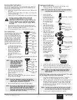
7. Disconnect the black and red wires coming from the gear
box housing. Disconnect the black and red wires from the
capacitors. Disconnect the black and red wires from the
motor.
8. Loosen and remove the four motor mounting screws.
9. Pull the motor out of the gear box housing.
NOTE: If the motor will not dislodge from the pump
housing:
• Remove the front cover plate.
• Using a rubber mallet, carefully tap on the front of
the motor crankshaft that extends through the slider
assembly.
10. With the motor removed, inspect the gears in the gear box
housing for damage or excessive wear. Replace the gears, if
necessary.
11. Install the new motor into the gear box housing.
NOTE: Rotate the motor fan manually until the armature
gear engages with the mating gear in the gear box
housing.
12. Secure the motor with the four motor mounting screws.
13. Push the new capacitors into their clip on the new motor.
14. Reconnect the wires (refer to the electrical schematic in the
Parts List section of this manual).
15. Slide the motor cover over the motor. Secure the motor cover
with the four motor cover screws.
Motor
cover
screw
Heat sink
assembly screw
Heat sink
assembly
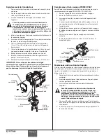
Fan
shroud
screw
Fan
shroud
Brush
cover
Motor
Motor
mounting
screw
Gear box
housing
Capacitors
Motor cover
BLA
CK
BLA
CK
RED
BLA
CK
RED
RED
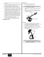
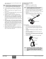
Replacing the Motor Brushes
Perform this procedure using Motor Brush Kit P/N 0508645.
1. Perform the Pressure Relief Procedure and unplug the sprayer.
2. Loosen and remove the four motor cover screws. Remove the
motor cover.
3. Loosen and remove the two fan shroud screws. Remove the
fan shroud.
4. Using a small screwdriver, pry off the two plastic brush covers.
5. Disconnect the black and red wires from the motor brushes.
Remove the motor brushes.
6. Install the new motor brushes and snap on the plastic brush
covers.
7. Reconnect the black and red wires from the motor brushes
(refer to the electrical schematic in the Parts List section of this
manual).
8. Position the fan shroud over the motor fan. Secure the fan
shroud with the two fan shroud screws.
9. Slide the motor cover over the motor. Secure the motor cover
with the four motor cover screws.
Replacing the Gears
1. Perform the Pressure Relief Procedure and unplug the sprayer.
2. Loosen and remove the four motor cover screws. Remove the
motor cover.
3. Disconnect the black and red wires coming from the gear box
housing.
4. Loosen and remove the four motor mounting screws.
5. Pull the motor out of the gear box housing.
NOTE: If the motor will not dislodge from the pump
housing:
• Remove the front cover plate.
• Using a rubber mallet, carefully tap on the front
of the motor crankshaft that extends through the
slider assembly.
6. Inspect the armature gear on the end of the motor for
damage or excessive wear. If this gear is completely worn out,
replace the entire motor.
7. Remove and inspect the 2nd stage gear for damage or
excessive wear. Replace if necessary.
8. Remove and inspect the crankshaft/gear assembly for damage
or excessive wear. Replace if necessary.
9. Reassemble the pump by reversing the above steps. During
reassembly, make sure the thrust washers is in place.
NOTE: Refill the gear box in the pump housing with five
ounces of grease (P/N 0293396).
Front cover
Gear box housing
Front cover screw
2nd stage gear
Thrust washer
Motor mounting
screw
Crankshaft/gear
assembly
Armature gear
Motor
Motor cover
Motor cover screw