


TPM 053
Version 1.0, May 30, 2017
Page | 18
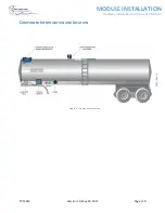
MODULE INSTALLATION
Gateway Installation and Operation Manual
E
LECTRICAL
I
NSTALLATION
When installing the Gateway and other electrical components, the following guidelines must be
followed:
•
Vehicle manufacturers usually have specific locations for electrical power access. These
locations are fuse protected to limit short-circuit current. Refer to the vehicle documentation or
contact the manufacturer for the recommended locations prior to the electrical installation.
•
For trailers, connect the Gateway system power and ground to the nose box electrical
connector. This will be a fused electrical power source from the truck. For trucks, connect
system power to a switched and fused accessory power connection from the battery. A switched
electrical power source is required to reduce battery drain while not in operation.
•
When making connections to the vehicle electrical ground, ensure that the wiring is terminated
at a battery ground terminal. Some metal components are electrically insulated from the battery
ground or bolted with painted surfaces causing a poor connection.
•
Wire splices and interconnections should be made inside a weather proof enclosure or junction
box to prevent premature failure due to corrosion.
•
Secure all wires and cabling with clips or cable ties.
•
Tighten all compression fittings.
Refer to the Tank Truck/Trailer Wiring Schematics in the Reference Drawings section of this manual.
Verify the Power Supply
•
Tank truck -
Switched accessory power
•
Tractor-trailer -
Trailer ABS power or dedicated switched accessory power
The Gateway module must be supplied power while driving, to periodically report position and activity.
The Gateway is supplied by continuous power from a source that is energized when the key switch is
turned on.
On trucks, this is called ‘Accessory Power’. On trailers, it is typically supplied by the anti
-lock braking
system (ABS) power from the J560 socket, pin-7.
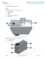
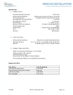
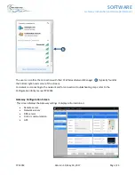
Connect the Gateway to the Junction Box
a)
Install the interconnect cable at the junction box and connect the free end into the 4-pin
connector at the bottom of the Gateway module, ensuring a fully seated connection
b)
Ensure cables are secured
Refer to the electrical options above for truck or trailer installation.
Connect the Finch Display to the Junction Box
Connect the Air Pressure Switch to the Junction Box (Trailer Installations)
Connect Electrical Power to Junction Box
Perform a Visual Inspection


