TIS RLY-8CH-16A Installation Manual Download Page 3

RELAY 8 CHANNELS 16 AMPS
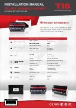
INSTALLATION MANUAL

MODEL: RLY-8CH-16A

TIS CONTROL LIMITED

RM 1502-p9 Easey CommBldg

253-261 Hennessy Rd Wanchai

Hong Kong

TEXAS INTELLIGENT SYSTEM LLC

SUITE# 610. 860 NORTH DOROTHY DR 

RICHARDSON

TX 75081.USA

Copyright © 2020 TIS, All Rights Reserved

TIS Logo is a Registered Trademark of Texas Intelligent System LLC in the 

United States of America. This company takes TIS Control Ltd. in other 

countries. All of the Specifications are subject to change without notice.

w w w . t i s c o n t r o l . c o m

Turn off the main electrical source before 

installation.

1

WARNING! HIGH VOLTAGE

INSTALLATION STEPS  

Mount the device on a DIN Rail inside an 

approved enclosure. The device can also 

be installed without the use of DIN Rail 

by two mounting screw holes.

2

+24

D+D-GND

+24

D+D-GND

Connect  RS485  data  cable  to  the  TIS-

BUS port as per the connection diagram. 

No need to loop the TIS-bus cable if 2 

DIN Rail modules are connected together 

from the side bus train terminal. 

3

GND(white-orange)&(white-brown)
D-(white-green)&(white-blue)
D+(blue-green)
+24V(brown-orange)

Cat5e connection

1

2

3

4

5

6

7

8

1

2

TIS-BUS

3

4

5

6

7

8

PRG

1
0

0

0

1

1

0

1

0

1

0

1

0

1

0

1

GND D-

D+ +24V

RLY-8CH-16A

WARNING! HIGH VOLTAGE!

!

To the TIS BUS Network

Cat5e

Complete the load connection, light, floor 

heating, and shutter as per the following 

steps:

LIGHTS / APPLIANCES /
FLOOR-HEATING CONNECTION

Connect  the  load  electrical  wires  to 

outputs  1-8.  Each  channel  can  control 

a  maximum  of  16A  loads.  The  installer 

should make sure not to overload the 

channels. 

Load neutral wire should be linked to the 

neutral connection in DB enclosure. 

4

GND(white-orange)&(white-brown)
D-(white-green)&(white-blue)
D+(blue-green)
+24V(brown-orange)

Cat5e connection

1.5 mm Electric Cable

2.5 mm Electric Cable

Connect To L

Connect To N

To the TIS BUS Network

Cat5e

1

2

3

4

5

6

7

8

1

2

TIS-BUS

3

4

5

6

7

8

PRG

1
0

0

0

1

1

0

1

0

1

0

1

0

1

0

1

RLY-8CH-16A

WARNING! HIGH VOLTAGE!

GND D- D+ +24V

!

Summary of Contents for RLY-8CH-16A

Page 1: ...ent Max continuous current 20A VAC TIS Bus Number of devices on 1 line Max 64 Bus voltage 12 32 V DC Current consumption Normal 12 mA 24 V DC Current consumption operation 35 mA 24 V DC Protection Rev...

Page 2: ...e a warranty as required by law A hologram warranty seal and product serial number are provided on each device Please send the description of the defect with Product S N to our dealer network Read Ins...

Page 3: ...d to loop the TIS bus cable if 2 DIN Rail modules are connected together from the side bus train terminal 3 GND white orange white brown D white green white blue D blue green 24V brown orange Cat5e co...

Page 4: ...onnect the shutter open wire to the first channel and the shutter close wire to the second channel The shutter neutral wire should be linked to the neutral connection in DB enclosure INSTALLATION STEP...

Page 5: ...m INSTALLATION STEPS MECHANICAL EMERGENCY SWITCH Turn on the power source and then test the loads by short pressing on the device s local override buttons 1 8 6 1 2 3 4 5 6 7 8 1 2 TIS BUS 3 4 5 6 7...

Page 6: ...LY 8CH 16A WARNING HIGH VOLTAGE Short press on any wall lights buttons on the Luna Mars Terre or others panels 2 1 TER 4G 45mm D 24V GND D 45mm 221 227A 12EM4 227A 12EM4 TER 4G A 45mm 45mm ADD 3R 5A A...

Page 7: ...fications are subject to change without notice w w w t i s c o n t r o l c o m Go to floor heater page on any wall panel with the floor heating function and press ON button to turn on the floor heatin...

Page 8: ...ress on the first button and then the second button that you want to combine as curtain control for example CH3 and CH4 2 1 2 3 4 5 6 7 8 1 2 TIS BUS 3 4 5 6 7 8 PRG 1 0 0 0 1 1 0 1 0 1 0 1 0 1 0 1 GN...

Page 9: ...5 1 2 3 4 5 6 7 8 1 2 TIS BUS 3 4 5 6 7 8 PRG 1 0 0 0 1 1 0 1 0 1 0 1 0 1 0 1 GND D D 24V RLY 8CH 16A WARNING HIGH VOLTAGE 6 Short press on any button on the Luna Mars Terre or others wall panels 6 T...

Page 10: ...seconds so the module can get new address Device PRG LED is not Blinking Device not Powered Reason Device is not powered on no TIS BUS 24V supply connected to the device Device Button LED ON but ligh...

Reviews: