background image

23

E

S

P

A

Ñ

O

L

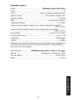
Especificaciones

Modelo .........................................................................

TIPPMANN

®

 Alpha Black

® 

Elite

Calibre .................................................................................................................................. .68
Acción ..................................................................... Sistema de válvula abierto Bolt Blow Back
Suministro de Aire .............................................................. aire comprimido, nitrógeno, o CO2
Alimentacion Bolas .....................................................................................................Gravedad
Gatillo  ...........................................................................................Semiautomático (Mecánico)
Longitud Barril estándar ...................................................................................... 12” / 30.48cm
Longitud (con barril estándar, no cilindro de aire, cubierta completamente colapsada) ............  

........................................................................................................................ 29.75” / 75.57cm
Longitud (con barril estándar, no cilindro de aire, cubierta totalmente extendida) ....................  

...................................................................................................................... 33.625” / 85.41cm
Alcance efectivo ...............................................................................150+ pies / 45.72+ metros
Peso (sin cilindro de aire) .................................................................................. 4.7 lbs / 2.1 Kg
Acabado final .................................................................................................... Enchape Negro
Velocidad .....................................................................................................................Ajustable
Siempre mida la velocidad de su marcador antes de jugar paintball y nunca haga disparos con 

velocidades que excedan los 300 pies (91.44 metros) por segundo. Ver instrucciones para 

Ajuste de Velocidad

 en la página 7.

Modelo Especifico .........................

TIPPMANN

®

 Alpha Black

®

 Elite con E-Trigger

Rata ciclo  ..................................................................Ajustable de 8 -15 disparos por segundo
Peso (sin cilindro) ............................................................................................4.93 lbs./2.24 kg
Batería  .........................................................................................................................9 Voltios 

Summary of Contents for Alpha black ELITE

Page 1: ...ANN 2955 Adams Center Road Fort Wayne IN 46803 USA P 260 749 6022 F 260 749 6619 www tippmann com Alpha black ELITE Paintball Marker Marcador Paintball Owner s Manual Manual del Usuario PLAY SMART PLAY STRONG ARMY STRONG S M ...

Page 2: ...os 18 años para la compra y uso Las personas menores de 18 años deben usar este producto bajo la supervisión de un adulto Lea el Manual del Usuario antes de usar este producto WARNING This is not a toy Misuse may cause serious injury or death Eye face and ear protection designed for paintball must be worn by the user and any person within range We recommend you be at least 18 years old to purchase...

Page 3: ...king device installed when not in a shooting situation see instructions on page 4 ADVERTENCIA La Seguridad es Su Responsabilidad Lea y familiaricese usted y cualquier otro usuario de este marcador con las instrucciones de seguridad de este manual Siga estas instrucciones cuando se utiliza trabajando transporte o almacenar este marcador Siempre mantenga el boton selector en seguro a menos que va a ...

Page 4: ...t enough cord elasticity to pull the cord retainer up over the top of the marker to remove the barrel blocking device for firing 3 After the cord length is properly adjusted lock the cord length by tying a knot in the cord against the back of the retainer as shown 4 Before and after playing inspect the barrel blocking device Replace the barrel blocking device if the device or cord is damaged or th...

Page 5: ...g Device Installation Instructions 4 Warning Liability Statement 6 Safety Is Your Responsibility 6 Getting Started 8 1 Install the Barrel 8 2 Install the Components to the Marker 8 3 Air CO2 Cylinder Installation 9 4 Loading the Hopper 9 5 Rate of Fire Adjustments 9 6 Firing the Marker 9 Velocity Adjustment 10 Unloading Your Marker 10 E Trigger Operating Instructions 10 1 Make the Marker Safe 10 2...

Page 6: ... safe and lawful use You must observe the same safety precautions as you would any firearm to assure the safety of not only yourself but everyone around you Outlined here are some general precautions to be aware of The user should at all times use caution and common sense when using this marker and always remember that the game of paintball can only survive and grow if it remains SAFE Do not load ...

Page 7: ...n playing the game of paintball Avoid exposing any skin when playing the game of paintball Even a light layer will absorb some of the impact and protect you from the paintballs Keep exposed skin away from escaping gas when installing or removing air CO2 cylinder or if the marker or air CO2 supply is leaking Compressed air CO2 and nitrogen gasses are very cold and can cause frostbite under certain ...

Page 8: ...ollapsible Stock a Find a 10 32 x 1 2 black screw B in the Maintenance Pack b Insert the Stock into the slots on the End Cap of the marker A c Insert and tighten the screw B Length Adjustment 1 Squeeze the Adjustment Lever 2 Slide the Stock together or apart to the desired length 3 Release the Adjustment Lever Feed Elbow a Refer to Figures 12 and 14 on pages 16 17 before attempting to install the ...

Page 9: ...der Removal instructions on page 14 and take your air CO2 cylinder to a C5 Certified Airsmith for inspection or contact the cylinder manufacturer 4 Loading the Hopper The barrel blocking device must be installed see page 4 and the Trigger Safety in Safe mode see page 6 a Make sure that the Hopper is clean and free of sharp edges or debris This keeps the paintballs from breaking prematurely and all...

Page 10: ...lodged in the chamber feed neck or barrel 5 Push the Trigger Safety to Safe mode see page 6 6 Reinstall the barrel blocking device see page 4 7 Read the Air CO2 Cylinder Warnings and Safety Tips on pages 13 14 before removing the air cylinder from your marker see removal instructions on page 14 E Trigger Operating Instructions Read and follow the E Trigger Operating Instructions completely before ...

Page 11: ... Mode 1 pull of the trigger fires 1 time This is the Factory Default Firing Mode Setting NOTE If pressing the power button failed to turn on the LED light see E Trigger Troubleshooting on page 12 To turn OFF the E Trigger press and hold the power button until the LED turns off then release the power button NOTE The E Trigger will shut off automatically after a prolonged period of inactivity 4 Chan...

Page 12: ...times to indicate Full Auto Fast mode Press and release the power button to choose the next firing mode cycles back to the first one SEMI AUTO Default firing mode see the beginning of this topic For first time Alpha Black Elite use you are now ready to go back to the Getting Started section steps 3 through 6 starting on page 9 NOTE If the marker does not fire see the E Trigger Troubleshooting sect...

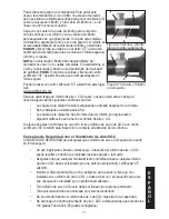
Page 13: ... place a mark 3 on the cylinder valve and place another mark 4 on the cylinder in line with the 3 mark as shown in Figure 8 Whenever you turn the cylinder during removal watch the marks on the cylinder and the cylinder valve to be sure that they rotate together If at any time these marks start to separate as shown in Figure 9 the cylinder is starting to unscrew from the cylinder valve and you must...

Page 14: ...of 250 degrees Fahrenheit 121 degrees Celsius or more must be destroyed by properly trained personnel Use appropriate gas for your cylinder Only use CO2 in a CO2 cylinder and only use compressed air in a compressed air cylinder Keep all cylinders out of the reach of children The air or CO2 cylinder should be inspected and hydrostatically retested at least every 5 years by a DOT licensed agency Kee...

Page 15: ... new air CO2 valve O Ring does not resolve an air CO2 leak do not attempt to repair the air CO2 cylinder Contact Tippmann Sports LLC your local paintball dealer or a C5 Certified Airsmith Cleaning and Maintenance To reduce the chance of an accidental discharge follow the Unloading Your Marker on page 10 and Air CO2 Cylinder Removal on page 14 Eye protection must be worn Do not disassemble a marker...

Page 16: ...r Oil when re assembling the barrel to the marker 4 To remove the Magazine 55 press two magazine tabs in and slide the magazine out the bottom of the marker 5 Turn the Velocity Screw 4 in until it stops Loosen two Air Supply Adapter ASA screws 39 and 40 6 To remove the Feed Elbow 41 press down the small Feed Elbow Latch 33 to unlock it then tilt the Feed Elbow out and slide it off the right side o...

Page 17: ...e fitting is out the Valve will slide out the back of the power tube NOTE Check the external Valve O Ring A and if damaged replace with a new one If the O Ring is damaged your marker will not function correctly Clean all parts and oil the O Rings 3 Reinstall the Valve into the Power Tube Insert the cleaned and oiled Valve into the Power Tube and align the holes of the Valve and Power Tube Apply te...

Page 18: ...e left receiver half make sure halves fit flush 3 Insert five of the six Receiver Screws shown in Figure 13 Leave the bottom left 38 as shown in Figure 13 out 4 Reinstall the Barrel Shroud and secure with the remaining Receiver Screw 38 from step 3 5 Attach the ASA 7 tighten two screws 39 and 40 NOTE 39 is the shorter adapter screw and goes in the front location as shown 6 Apply marker oil onto th...

Page 19: ...o it moves freely 7 Insert Magnet in slot below armature as shown 8 Double check that all parts are in place as shown 9 Place battery connector through left receiver half Make sure the magnet fits into left receiver half slot so it does not break and wires are not pinched as you place left half on right half so the halves fit flush Markers with E Trigger now go to step 2 on page 18 WARNING To prev...

Page 20: ...arts Diagram Tippmann Service Department 1 800 533 4831 www tippmann com 56 49 2 35 8 42 2 45 46 41 47 43 51 15 63 61 59 57 58 29 20 34 33 28 25 27 22 62 64 60 32 31 30 27 26 48 44 1 23 24 21 A 5 F C C B E G D 52 V alve C omponents ...

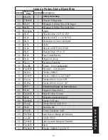
Page 21: ...1 E N G L I S H WARNING Do not disassemble this marker while it is pressurized Do not pressurize a partially assembled marker 37 55 54 53 37 50 37 12 6 39 40 7 19 15 14 13 11 9 10 5 4 3 16 18 17 49 38 36 ...

Page 22: ... 2 O Ring C U 70A 2 012 D 98 32 1 Comp Spring 0 983 Fl X 0 404 O D E CA 27 1 Valve Seat F PA 31A 1 Snap Ring Internal G 98 PL 1 Valve Plunger 6 98 09N 1 Gas Line 7 98 06 1 Air Supply Adapter ASA 8 98 26 2 Screw BHCS 9 TA02011 1 Rear Bolt 10 98 12A 1 O Ring C U 90A 2 019 11 TA05005 1 Rear Bolt Plug 12 98 13 1 Rear Bolt Handle 13 CA 14 1 Spring Comp 4 392 F L x 0 189 O D 14 CA 15 1 Pin Flt Fillister...

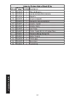
Page 23: ...t Sight Spring 33 98 14 1 Feed Elbow Latch 34 FA 18 1 Ball Latch 35 CA 08B 2 Nut 10 32 Square MS 36 TA06039 1 Receiver Left Side 37 98 01A 3 Screw LHSHCS 38 TA06015 3 Screw LHSHCS 10 32 X 0 840 39 PL 01A 1 Screw BHCS 10 32 X 875 40 98 06A 1 Screw BHCS 10 32 X 1 125 98 E 1 Feed Elbow Assembly 41 98 04 1 Feed Elbow 42 TA02076 2 Dowel Pin Knurled 43 98 43 1 Feed Elbow Latch 44 TA05052 2 Screw Phil Tr...

Page 24: ...k Magazine 56 TA06201 1 Alpha Black Collapsible Stock TA06210 1 Barrel Shroud Assembly 57 TA06071 1 Shroud Upper 58 TA06072 1 Shroud Lower 59 TA06070 1 Front Sight 60 TA06077 4 Screw Plastite 6 19 X 1 2 Pan Head TA06211 1 Carrying Handle Assembly 61 TA06073 1 Carrying Handle 62 TA06076 2 Clamping Screw 63 TA06075 1 Clamping Bar 64 TA06074 2 Clamping Nut ...

Page 25: ...dard barrel no air cylinder stock fully extended 33 625 85 41cm Effective Range 150 feet 45 72 meters Weight without air supply cylinder 4 7 lbs 2 1 Kg Finish Black Powder Coated Velocity Adjustable Always measure your marker s velocity before playing paintball and never shoot at velocities in excess of 300 feet 91 44 meters per second See Velocity Adjustment instructions on page 10 Model Specific...

Page 26: ...original retail sale Further Tippmann warrants to the original purchaser that it will make any repairs or replacements necessary to correct defects in material or workmanship at no charge to you for Tippmann Accessories for a period of ninety 90 days from the date of original retail sale All Tippmann asks is that you properly maintain and care for the Marker and Accessories collectively the Produc...

Page 27: ...on Warranty Repairs When shipping the Product to Tippmann for warranty or non warranty repair 1 If you have aftermarket parts on your Marker please test the Marker with original stock parts before returning the Marker for service or repair 2 Always unload page 10 and remove the air CO2 supply from the marker page 14 Do not ship the air CO2 supply cylinder if it is not completely empty 3 Ship the P...

Page 28: ...28 E N G L I S H NOTES ...

Page 29: ... cordón para poder jalar el cordón retenedor por encima del marcador para así remover la mecanismo de bloqueo del barril 3 Una vez que la longitud del cordón elástico se ha definido adecuadamente haga un nudo ajustándolo contra el seguro plástico como se observa 4 Antes y después de jugar inspeccione la mecanismo de bloqueo del barril del barril y reemplace bolsa o el cordón elástico si presentan ...

Page 30: ...Bloqueo del Barril 1 Advertencia Declaracion de Responsabilidad 3 Inicio 5 1 Instalación Del Barril 5 2 Instalación de los Componentes en el Marcador 5 3 Instalacion del cilindro de Aire CO2 6 4 Cargando la Tolva de Munición 6 5 Ajuste de la Rata de Disparo 6 6 Disparando el Marcador 6 Ajuste de la Velocidad 7 Descargando Su Marcador 7 Instrucciones de Manejo de la E Trigger 7 1 Haga que su marcad...

Page 31: ...de seguridad que tendría con un arma de fuego asegurándose no solo por su seguridad sino por cualquiera alrededor de usted Aqui encontrara algunas de las precauciones que debe tener en cuenta El usuario debe ser cauteloso en todo momento cuando este usando este marcador y tenga siempre presente que el deporte de Paintball solo puede sobrevivir y crecer si este se mantiene SEGURO No cargue o dispar...

Page 32: ...or mientras este presurizado Vístase apropiadamente cuando juegue paintball Evite exponer cualquier parte de la piel cuando juegue paintball Aún algo delgado absorberá parte del impacto y lo protegerá de las bolas de pintura Mantenga las áreas de piel expuesta alejadas en caso de algún escape de gas cuando instale o remueva el cilindro de suministro de aire El aire comprimido y CO2 son gases muy f...

Page 33: ...a que este dentro del radio de alcance 1 Instalación del Barril a Asegúrese que el empaque O 15 del barril está colocado al final del Barril b Deslice el barril dentro de la carcasa y atorníllelo dando vuelta en el sentido a las manecillas del reloj 2 Instalación de los Componentes en el Marcador Conjunto Plegable a Encuentre un tornillo negro B 10 32 x 1 2 en el Paquete de Mantenimiento b Inserte...

Page 34: ... su totalidad el pasador de la valvula puede estar muy corto o el empaque de la valvula no esta bueno Siga las instrucciones de Remocion del Cilindro de Aire CO2 en la página 12 y lleve su cilindro de Aire CO2 a un experto con certificación C5 para inspección o contacte al fabricante del cilindro 4 Cargando la Tolva de Munición El mecanismo de bloqueo del barril debe estar instalado ver página 1 y...

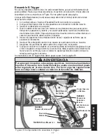
Page 35: ... 3 En el área designada para disparos remueva el mecanismo de bloqueo del barril y ponga la seguridad del gatillo en función de disparo 4 Apunte su marcador en dirección segura y dispare varias veces para asegúrese de que no queden bolas de pintura remanentes en la cámara en el cuello de alimentación o en el barril 5 Empuje la seguridad del Gatillo a Seguro ver página 3 6 Reinstale el mecanismo de...

Page 36: ... del mango La Instalacion de la batería ha sido terminada NOTA La E Trigger tiene un indicador para batería baja La luz verde Lista para Disparo se verá en el tablero LED y cambiara a roja cuando la batería este con energía baja y requiere ser reemplazada 3 Operación Para encender la E Trigger en operacion normal Lista para disparar a Sin hacer presión sobre el gatillo use un objeto pequeño como u...

Page 37: ... de pintura por Segundo bps Para disparar usando la función Normal Auto Completa usted debe jalar el gatillo 2 veces en un lapso de 1 segundo y sostener el gatillo una tercera para disparar 12 bps hasta que usted libere el gatillo Jala el gatillo subsecuentemente en 1 segundo continuara disparando en función Normal Auto Completa Si usted no jala el gatillo después de 1 segundo o mayor tiempo usted...

Page 38: ...ara Asegúrese de que la seguridad del gatillo esta puesta en posición de DISPARO y que el marcador tenga suficiente suministro de aire disponible Asegúrese de que el marcador este engatillado PROBLEMA La luz verde LED que indica Listo para Disparar cambio a rojo Esta es una condición que se presenta cuando la batería esta baja en potencia El marcador presentara variaciones en su desempeño cuando l...

Page 39: ...reemplazada o alterada después de la compra Se ha instalado un sistema anti sifón La válvula de la unidad se ha sido removida del cilindro por alguna razón Alguna modificación se ha hecho al cilindro de aire o CO Si alguna de estas condiciones ha ocurrido tome el cilindro de aire o de CO2 a un centro certificado C5 Airsmith para inspección o contacte al fabricante de los cilindros Consejos de Segu...

Page 40: ... ser usados por el usuario y cualquier persona que se encuentre en radio de juego 3 Siga las instrucciones de Descargando Su Marcador en la página 7 4 Mire las marcas en el cilindro y en la válvula como se observa en la figura 9 en la página 11 cuando de vuelta al cilindro de vuelta aproximadamente en sentido contrario a las agujas del reloj 5 Retire la mecanismo de bloqueo del barril del barril y...

Page 41: ... presurizado No presurise un marcador parcialmente ensamblado Siga las advertencias enumeradas en el cilindro de suministro de aire para manipulación y almacenamiento Familiarizese con todas las instrucciones enumeradas para el suministro de aire y el adaptador Si tiene alguna duda contacte al fabricante No use solventes o derivados a base de pétroleo No use solventes o limpiadores en aerosol NOTA...

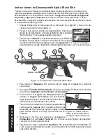
Page 42: ...tificado para Marcadores 4 Para remover el Magazine 55 presione las dos aletas en el magazine y deslícelo hacia afuera 5 De vuelta al Tornillo de Velocidad 4 hasta que se detenga Soltando los dos tornillos 39 y 40 del Adaptador de Suministro de Aire ASA 6 Para remover el Angulo de Alimentación 41 presione el Angulo del Cerrojo 33 para liberarlo luego levante el ángulo de Alimentación hacia afuera ...

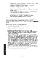
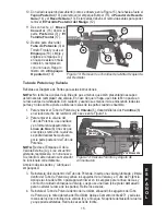
Page 43: ...idor como se ve en la Figura 14 2 Para remover la válvula del Tubo de Potencia use una llave y en forma lenta desatornille la Línea de Gas 6 Una vez que el acople es removido la válvula se podrá deslizar hacia afuera por la parte posterior del Tubo de Potencia NOTA Revise el Empaque O de la Válvula Externa A y si se encuentra alterada reemplácela con una nueva Si el Anillo O esta dañado su marcado...

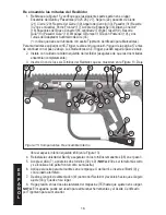
Page 44: ...cuidado la mitad izquierda del recibidor asegúrese de que las dos mitades ensamblan completamente 3 Inserte cinco de los seis Tornillos del Recibidor que se muestran en la Figura 13 Deje libre el espacio inferior izquierdo 38 en la Figura 13 4 Reinstale la cubierta del Barril y asegurela con los tornillos remanentes 38 en el paso 3 5 Acople el ASA 7 apriete los dos tornillos 39 y 40 NOTA 39 es el ...

Page 45: ...2 cajuelas de tal forma que se pueda mover libremente 6 Inserte el Disco Magnético dentro de la cajuela de la armadura como se muestra 7 Asegúrese de que todas las partes están en su lugar como se muestra 8 Coloque el conector de la batería en la mitad izquierda del recibidor Asegúrese de que el disco magnético encaja dentro de la ranura de la mitad izquierda del recibidor de tal manera que no se ...

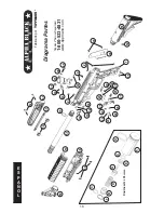
Page 46: ...N Diagrama Partes Tippmann Service Department 1 800 533 4831 www tippmann com 56 49 2 35 8 42 2 45 46 41 47 43 51 15 63 61 59 57 58 29 20 34 33 28 25 27 22 62 64 60 32 31 30 27 26 48 44 1 23 24 21 A 5 F C C B E G D 52 C omponentes V álvula ...

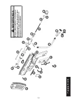
Page 47: ... L ADVERTENCIA Ne pas dêsassembler ce marqueur pendant que c est pressurisé avec l air CO2 Ne pas pressuriser un marqueur moitié assemblé 37 55 54 53 37 50 37 12 6 39 40 7 19 15 14 13 11 9 10 5 4 3 16 18 17 49 38 36 ...

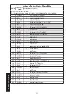
Page 48: ...ue O C U 70A 2 012 D 98 32 1 Resorte 0 983 Fl X 0 404 O D E CA 27 1 Valvula Seat F PA 31A 1 Anillo Interno G 98 PL 1 Valvula Plunger 6 98 09N 1 Linea de Gas 7 98 06 1 Adaptador suminstro de aire ASA 8 98 26 2 Tornillo BHCS 9 TA02011 1 Bolt Trasero 10 98 12A 1 Empaque O C U 90A 2 019 11 TA05005 1 Tapon Bolt Trasero 12 98 13 1 Manija Bolt Trasero 13 CA 14 1 Resorte 4 392 F L x 0 189 O D 14 CA 15 1 P...

Page 49: ...lo del cerrojo 34 FA 18 1 Acople de Enganche 35 CA 08B 2 Tuerca 10 32 Cuadrada MS 36 TA06039 1 Recibidor Lado Izquierdo 37 98 01A 3 Tornillo LHSHCS 38 TA06015 3 Tornillo LHSHCS 10 32 X 0 840 39 PL 01A 1 Tornillo BHCS 10 32 X 875 40 98 06A 1 Tornillo BHCS 10 32 X 1 125 98 E 1 Ensamble Angulo de Alimentacion 41 98 04 1 Angulo de Alimentacion 42 TA02076 2 Pasador Doble Knurled 43 98 43 1 Enganche Ang...

Page 50: ... TA06203 1 Magazine 56 TA06201 1 Conjunto Colapsible TA06210 1 Ensamble cubierta del Barril 57 TA06071 1 Cubierta Superior 58 TA06072 1 Cubierta Inferior 59 TA06070 1 Lado Frontal 60 TA06077 4 Tornillo Plastite 6 19 X 1 2 Cabeza Plana TA06211 1 Ensamble Manija Transporte 61 TA06073 1 Manija Trasporte 62 TA06076 2 Tornillo grapa 63 TA06075 1 Barra Grapa 64 TA06074 2 Tuerca Grapa ...

Page 51: ...n barril estándar no cilindro de aire cubierta totalmente extendida 33 625 85 41cm Alcance efectivo 150 pies 45 72 metros Peso sin cilindro de aire 4 7 lbs 2 1 Kg Acabado final Enchape Negro Velocidad Ajustable Siempre mida la velocidad de su marcador antes de jugar paintball y nunca haga disparos con velocidades que excedan los 300 pies 91 44 metros por segundo Ver instrucciones para Ajuste de Ve...

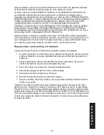
Page 52: ...en su Marcador por un periodo de uno 1 año desde la fecha de su compra Es mas Tippmann le garantiza al comprador original que hará toda reparación necesaria o reemplazos necesarios para corregir defectos en partes o mano de obra sin costo para usted Para Accesorios Tippmann por un periodo de noventa 90 días desde el día de la compra Todo lo que Tippmann le pide es que haga el mantenimiento apropia...

Page 53: ...r de un estado a otro o de una nación a otra Reparaciones con Garantia y sin Garantia Cuando enviar este Producto a Tippmann por garantia o repacion sin garantia 1 Si usted tiene partes en su Marcador que se adquirieron después de compra por favor pruebe su Marcador con partes originales antes de enviar el Marcador para servicio o reparación 2 Siempre descargue y remueva el suministro de aire de s...

Page 54: ...26 E S P A Ñ O L NOTAS ...

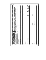
Page 55: ...Your Name print Phone Country Address Country 2955 ADAMS CENTER ROAD FT WAYNE IN 46803 USA Male Age Female TIPPMANN E mail City State Zip City State Zip Warranty Registration online at www tippmann com or complete this warranty card and mail to Tippmann ...

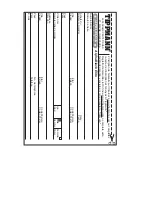
Page 56: ...N 46803 USA Mâle Hombre Âge Edad Femelle Mujer TIPPMANN E mail Ville État Code Postale Ciudad Estado Código Postal Ville État Code Postale Ciudad Estado Código Postal L Insription de Garantie sur l internet à www tippmann com ou complétez la carte de d inscription et l envoyez à Tippmann Registro de Garantia via On line a www tippmann com o complete esta tarjeta de garantía y enviela por correo re...

Page 57: ...NOTES NOTAS ...

Page 58: ...NOTES NOTAS ...

Page 59: ...NOTES NOTAS ...

Page 60: ...NOTES NOTAS ...

Page 61: ...NOTES NOTAS ...

Page 62: ...NOTES NOTAS ...

Page 63: ...NOTES NOTAS ...

Page 64: ......

Reviews: