

Voltage
The voltage used to test should be high enough so that in areas where the coating is electrically
weaker, due to a flow or discontinuity, there is sufficient voltage to break down the gap or
insulation between the probe and the substrate. When this breakdown occurs the current flows
from the probe, through the substrate and back into the holiday detector, completing a circuit
and thereby triggering an alarm to signal a flaw has been detected. As the high voltage method
can locate any area where the coating is weaker than specified, this method allows you to
detect flaws that don’t go all the way down to the substrate, such as cratering for example, as
well as voids within the coating.
The Tinker & Rasor APS Holiday Detector includes an integrated voltmeter displayed on the
front panel of the main instrument. The LCD screen of the voltmeter measures and displays the
output voltage of the holiday detector. This display gives the user the ability to tune the APS to
a specific voltage with in increment in 100V steps.
Correct voltage output for a given thickness of coating has long been a matter of controversy.
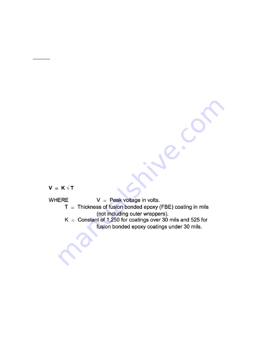
However, recent formulas have been suggested which may be used as a guide for correct peak
voltages on various coating thickness. The calculation is as follows:
NACE International Standard RP0274, RP0490 Formula
These formulas, when applied to a coating of 3/32” thickness and with a constant of 1,250,
would indicate an applied voltage of 12,500 volts peak or a coating of 16 mil thickness with a
constant of 525 would indicate an applied voltage of 2,100 volts. A common practice used in
setting inspection voltages in the field is to adjust the output voltage by visual observation. It is
the consensus that spark discharge at least twice the thickness of the coating will give adequate
inspection voltage and compensate for determining inspection voltage, it should be done while
the electrode is in the normal operating position and under actual grounding conditions.