


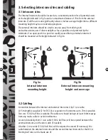


4
7
9
15
Wall surface
3mm
External
intercom
4. Fixing Intercoms
4.1 External intercom
Important: To give the best possible waterproofi ng and appearance we
recommend taking the wiring through the exterior wall directly over the wiring
terminals of the If the surface to be fi xed to is not even (e.g. pebbledash or
brickwork with raised pointing) we recommend the use of at least 10mm (3/8")
thick marine ply as a mounting plate between the wall and the intercom to
give a fl at surface for its 3 point fi xing.
Use the template provided to mark the positions of the three fi xing holes. Drill and, if
necessary, plug these holes for No. 8 roundhead screws.
Drive the top two No. 8 roundhead screws in leaving 3mm of the shank exposed (see fi g 4).
Fig 4
The third screw is used to secure the angle bracket (15) to the wall (see fi g 5).
Pass the cable(s) through the wall hole and terminate the cable from the internal intercom
ensuring that the brown and red wires are connected to the terminals of the same colour
on the external intercom (particularly important if an extension cable is used).
If a DCC4 is being installed then a second cable will be required to connect to the
additional internal intercom maintaining polarity as before.
If a door catch is to be used connect an additional two core cable to the terminals on the
external intercom marked door opener (not polarity conscious).
Offer up the external intercom to the fi xing points feeding the cable(s) back through the
wall as necessary. Locate the larger part of the keyhole fi xings on the heads of the two
fi xing screws (see fi g 5) and, keeping the rear of the case clear of the angle bracket (15),
push the external intercom downwards to locate the screws on the narrower part of the
keyhole fi xing.
Push the lower part of the external intercom towards the wall taking care
to locate the angle bracket (15) in the slot (9). Insert the screw supplied
through the countersunk hole in the lower edge of the external intercom and screw home.
If the fi xing surface is uneven it may be necessary to increase the exposed shank of one or
both of the top fi xing screws to get a satisfactory fi t.
Fig 5
DCC3_DCC4_Instructs_1.3.indd 5
DCC3_DCC4_Instructs_1.3.indd 5
30/1/07 11:05:34 am
30/1/07 11:05:34 am


