


1
NAME PLATE
NAME PLATE
1
4
6
3
5
16
11
12
13
17
15
2
10
14
18
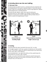
1. Introduction
The DCC3/DCC4 Door Entry System enhances entry security by enabling the user
to recognise the visitor by audible and visual means before openiing the door.
The external intercom incorporates LED lighting to illuminate the visitor for the
camera. This type of lighting has an indefi nte life.
An electric door catch (not supplied) is available as an optional extra for the
DCC3/DCC4 to make the door opening automatic.
The external and internal intercoms are connected by a two core cable. With
the cable supplied the distance between these units is limited to 15m. By using
13/0.2 bell fl ex cable this distance can be increased to a maximum of 70m
2. Product Overview
If operation with an electric door catch is required then part DCLR is a fail
(power off) secure catch available from Timeguard. An additional two core
cable run (using 13/0.2 bell fl ex) will be required between internal intercom and
door catch.
Fig 1 - Component Parts
1. External
intercom.
2. Internal
intercom.
3. Name
plate.
4. Loudspeaker.
5.
Mains on indicator.
6. Call
button.
7. Keyhole
fi
xing.
8. Screw
terminals.
9.
Slot for angle bracket (15).
10. Wall mounting plate.
11. Monitor on button.
12. Monitor off button.
13. Door open button.
14. Brightness - three position
switch.
15. Angle
bracket.
16. Volume adjust - three
position switch.
17. Connecting
cable.
18. Internal intercom handset
DCC3_DCC4_Instructs_1.3.indd 2
DCC3_DCC4_Instructs_1.3.indd 2
30/1/07 11:05:33 am
30/1/07 11:05:33 am


