Tiltamax Nucleus-M WLC-T03 User Manual Download Page 9

1

3

2

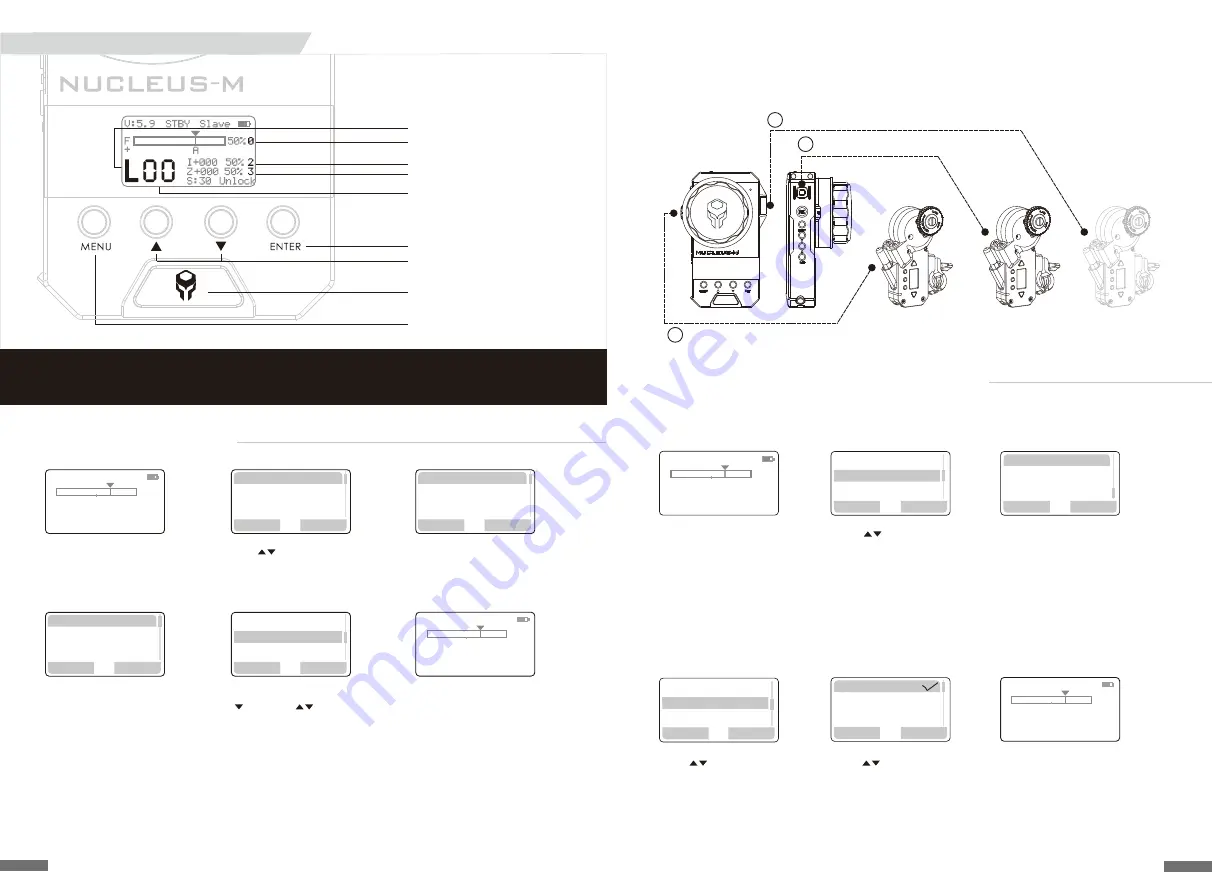
2. Assigning the Motor Numbers to the FIZ Unit

1. Press

M

ENU

to enter the 

Main Menu

2. Use           to highlight  

"MOTOR" - press

ENTER


to conrm

3. Choose the corresponding 
controller of the FIZ Unit to the 
designated function of each Motor. 

For Example, pair the Motor on the 
Focus gear of the Lens to the Focus 
Knob on the FIZ. In this case, that 
Motor has been assigned as Motor 
Number 1.

Highlight "FOCUS" and press

E

NTER


4. Use           to highlight "SYNC" -
press

E

NTER

to conrm  

5. Use           to highlight "Motor 1" -  
press

E

NTER

to conrm. 

Conrmation is identied by a 
check mark. If a Motor Number has 
no check mark, it is not synced 
with a controller on the FIZ 

6. Repeat Steps 1 - 5, to assign the 
Zoom and Iris Motor to the FIZ Unit. 

Press

M

ENU

to return to the 

Home Screen. If the display looks like 
the picture above, then all 3 Motors 
have been synced properly

Note: Motors cannot share the same Motor Number. A Motor can identify if its Motor 
Number is being repeated and will automatically cancel the last Motor Number assigned  

MOTOR 1

MOTOR 2

MOTOR 3

(FOCUS)

(ZOOM)

(

IRIS Sold Separately

)

FIZ Unit - FOCUS Knob

FIZ Unit - IRIS Wheel

FIZ Unit - ZOOM Joystick

Below is a Figure for conceptual demonstration purposes depicting a default assignment 

of the FIZ Unit and 3Motors. Use the example below for quick start and troubleshooting 

16

Wireless

Motor

Function

Torque

SYNC

Direction

Back

Enter

Motor


1

STBY Slave

F

0

A

I+000 50%


2

Z+000


50%


3

V:5.9

S:30 Unlock

50%

01

+

M

Focus

ZOOM
IRI

STBY

Master

F

1

A

I+000 50%


2

Z+000


50%


3

V:5.9

S:30 Unlock

50%

01

+

M

Motor


2

Motor


3

Back

Set

Back

Enter

Back

Enter

Wireless Signal Range
MOTOR Number (F=Focus)

MOTOR Number (I=Iris) 
MOTOR Number  (Z=Zoom) 

CHANNEL

ENTER Button

UP / DOWN Buttons

POWER Button

MENU Button

1. Setting the FIZ Unit's Channel


1. From the Home Screen,
use

MENU

to open the 

Menu System  

2. Use         to highlight "WIRELESS"- 

press

ENTER

to conrm  

3.With "

2.4G

" highlighted, 

press

E

NTER

t

o conrm

4. Continue pressing

E

NTER

until "M" is selected. This value 
represents the "

2

.

4G

" or Long 

Range Value:  

H MAX:

 Furthest Wireless Distance, 

     High Power Consumption 

Medium

:

 Recommended Wireless Distance, 

     Average Power Consumption

MIN

Short Wireless Distance, 

     Low Power Consumption

OFF: 

No Wireless Signal Transmitted

     used when hardwiring FIZ to Motor

5. Highlight CHANNEL by pressing
        , then use           to change
the Channel Number. Available
Channels range from 00-

15

. Set

the CHANNEL to "0

2

"     

6. Press

M

ENU

to return to the 

Home Screen. If the screen looks 
like the image above then the FIZ 
Unit's Channel has been set   

15

Syncing FIZ Hand Unit with Motors

REC

Master

F

0

A

I+000 50%


2

Z+000


50%


3

V:5.9

S:30 Unlock

50%

02

+

M

REC

Master

F

0

A

I+000 50%


2

Z+000


50%


3

V:5.9

S:30 Unlock

50%

00

+

L

Back

Enter

2

.

4G

Mode

   M

Channel 00

设 置

返 回

Back

Enter

Wireless

Motor
Function

设 置

返 回

The FIZ Unit Channel Number must Match one of the daisy-chained Motor Channels.

The FIZ Unit defaults to MASTER mode. To use the Handles, set FIZ Unit to SLAVE mode.

Note:

Mode

   M

Channel 02

Summary of Contents for Nucleus-M WLC-T03

Page 1: ...TILTA TECHNOLOGY CO LTD TEL 86 0755 33185005 Fax 86 0755 33185003 Add 2nd Floor Building B Qiaode High Technology Park Road No 7 Guangming New Dist Shenzhen 518125 TEL 1 818 561 4991 Address 2801 W Ma...

Page 2: ...o Arri Standard Rosette Adaptor Handle to Gimbal Bar Adaptor 25mm 30mm diameter Waterproof Safety Case Follow Focus Ring 0 4 0 5 0 6 Gear Follow Focus Ring x2 Long Distance Wireless Module 02 Product...

Page 3: ...T03M 5 1 2 3 4 6 9 12 11 7 8 10 FIZ Hand Unit Transmitter 02 REC Button 03 FUNCTION Button 04 DELETE Button 05 MARKER Button 06 CALIBRATE Button 07 MENU Button 10 ENTER Button 11 USB port 14 18650 Ba...

Page 4: ...stick LED Indicator Knob LED Indicator 12 Z LED 13 F LED Component Functions Right Wireless Handle 06 6 Z F 2 3 18650 9 7 11 10 8 12 13 4 5 1 Component Functions Controller 04 MENU Button 01 RECORD Bu...

Page 5: ...gin just as if it were a cine lens Add the follow focus ring to the lens Secure it tightly Make sure the fastener is not in a position where the motor s gear will hit it during it s calibration run On...

Page 6: ...and activate the camera s R S if the camera port is capable of power out and R S such as the 3 pin LEMO ports on the Tilta Alexa Mini and RED DSMC2 Cages For Example ARRI XT RS port TILTA FOR ALEXA MI...

Page 7: ...nd secure connection via large thumb screw 2 Attach Universal Gimbal Adaptor to Gimbal Ring Repeat for opposite side Handle to Universal Gimbal Adaptor with Rosette Assembly 1 2 Nucleus M Gravity Gimb...

Page 8: ...is Power Key Off Up Keys Select Other Keys Cancel V7 8 STBY FREE 000 FREE 000 S 30 R 01 1 K L L J 2 Power Off in 3S 1 FIZ Hand Unit Hold POWER to Open the Main Menu Turn Off 1 1 Hold POWER then releas...

Page 9: ...Motor 1 STBY Slave F 0 A I 000 50 2 Z 000 50 3 V 5 9 S 30 Unlock 50 01 M Focus ZOOM IRI STBY Master F 1 A I 000 50 2 Z 000 50 3 V 5 9 S 30 Unlock 50 01 M Motor 2 Motor 3 Back Set Back Enter Back Enter...

Page 10: ...e click ENTER to con rm 4 Press MENU to return to the Home Screen If the display looks like the image above then the Motor Number has been set Lastly repeat the steps above to match the corresponding...

Page 11: ...ome Screen double click MENU to open the Menu System Use to select KNOB NO double click MENU to con rm 2 When a Motor has a been assigned a Motor No that number corresponds to the value that can be se...

Page 12: ...focus gears and hard stops calibrate from the FIZ unit by holding down CAL The screen will show a 3 second countdown Holding down CAL on the motor will also trigger a calibration Lenses without hard s...

Page 13: ...2 J ZOOM A B Z F Setting the Range Hard Stops on Handles 1 Setting the Rotation Degree on the Knob Some lenses have long focus throws To compensate for this the Handle s knob can be set to various ro...

Page 14: ...V 5 9 S 30 Unlock 50 00 L Back Focus ZOOM IRIS Enter Back Enter Torque SYNC Direction Back Enter System Motor Wireless Back Motor 1 Motor 2 Motor 3 SET 2 Change the Language 3 2 4G and CHANNEL Click o...

Page 15: ...the Speed Controller Setting Set the Iris to 0 by having no Motor No synced to the Iris controller on the FIZ The Home Screen will now show an S where I used to be S refers to speed Now the speed of t...

Page 16: ...tion CCW JoyStick Dir JoyStick Tor JoyStick SPD Calibrate Kb JoyStick Motor Direction CCW JoyStick Motor Direction CW JoyStick Tor JoyStick SPD Calibrate Kb Restore JoyStick Motor Torque 90 5 Motor In...

Page 17: ...n 11 Calibrate Handle Knob 1 If the motor spins one way then rapidly spins the other way in the same instance 2 If the Knob is completely rotated to the end and the Knob Rotation Value on the display...

Page 18: ...harmful interference in a residential installation This equipment generates uses and can radiate radio frequency energy and if not installed and used in accordance with the instructions may cause har...

Reviews: