


ASSEMBLY
© 2019 Alamo Group Inc.
ASSEMBL
Y
Assembly Section 2-
4
1) Remove plastic cover over flywheel access at left, rear
of engine, front of flywheel housing.
2) Use Crankshaft Turning tool #JDE83 to turn flywheel in
“engine operating direction” (turn tool counter-clockwise
when viewing aft into flywheel housing) until timing pin
engages timing hole in flywheel. Note, the shoulder at
outboard end of #JDE83 tool may interfere with tapped
boss in engine block casting, and may require chamfering
of the edge of the shoulder to allow tool to align with bore
in flywheel housing.
3) Loosen, relieve tension in both belts.
4) Remove bolts securing front, sheet metal pulley, re-
move pulley.
5) Remove center bolt of rear pulley, remove pulley with
puller.
6) Then remove Woodruff key, and discard.
7) Remove four (4) bolts securing fan shroud.
8) Move fan shroud aft to allow access to four (4) bolts
securing fan.
9) Remove the fan bolts, install spacer #R282106, rein-
stall fan and secure with new bolts, #19M8039.
10) Reinstall fan shroud with existing hardware.
11) Clean Sleeve, #DZ10755 and nose of crankshaft.
12) Install Sleeve, #DZ10755 onto crankshaft, and align
accordingly to the spring pin in the timing wheel.
13) Lightly oil the tapered surfaces of the Collet, #80727,
Replacement Pulley, #SU35089, and Cap Screws,
#19H3131, and install Washer, #24M7238 onto cap
screws.
14) Insert Collet, #R80727 into Pulley, #SU35089, and
install to two (2) Cap Screws with Washers into Pulley at
180° across from each other, and thread in 3-5 turns.
15) Install Collet/Pulley assembly on to the Sleeve,
#DZ10755 and crankshaft, and align the mark on the
Pulley with the mark on the timing gear cover.
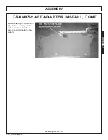
16) Install Spacer, #DZ107571, and Bolt, #R132865, then
torque Bolt to 111 Ft.-Lbs.
CRANKSHAFT ADAPTER INSTALL, CONT.
Summary of Contents for JD5075E T4F
Page 4: ......
Page 6: ......
Page 7: ...SAFETY SECTION...
Page 18: ...Side Rtry Safety Section 1 12 SAFETY SAFETY...
Page 27: ...Side Rtry Safety Section 1 21 SAFETY SAFETY 00756059 MOWER DECK 34852 HYDRAULIC TANK...
Page 30: ...Side Rtry Safety Section 1 24 SAFETY SAFETY...
Page 31: ...Assembly Section 2 1 ASSEMBLY SECTION JD 5075E T4F SIDE ROTARY...
Page 44: ...ASSEMBLY Assembly Section 2 14 SIDE MOWER HYDRAULIC DIAGRAM ASM C 0090 JD5075E...
Page 49: ...Operation Section 3 1 2013 Alamo Group Inc OPERATION SECTION...
Page 90: ...OPERATION SIDE ROTARY Operation Section 3 42 2014 Alamo Group Inc OPERATION...
Page 91: ...Maintenance Section 4 1 2014 Alamo Group Inc MAINTENANCE SECTION...
Page 114: ...MAINTENANCE SIDE ROTARY Maintenance Section 4 24 2014 Alamo Group Inc MAINTENANCE...
Page 115: ...PARTS SECTION JD5075E T4F SIDE ROTARY...
Page 117: ...PARTS ORDERING GUIDE 2019 Alamo Group Inc Parts Section 3 JD5075E SIDE ROTARY...
Page 118: ...TRACTOR MOUNT KIT 2019 Alamo Group Inc Parts Section 4 JD5075E SIDE ROTARY...
Page 120: ...TRACTOR MOUNT KIT HYDRAULICS 2019 Alamo Group Inc Parts Section 6 JD5075E SIDE ROTARY...
Page 124: ...DRAFT BEAM TSR MOWER 2019 Alamo Group Inc Parts Section 10 JD5075E SIDE ROTARY...
Page 126: ...DRAFT BEAM TM MOWER 2019 Alamo Group Inc Parts Section 12 JD5075E SIDE ROTARY...
Page 129: ...NOTES 2019 Alamo Group Inc Parts Section 15 JD5075E SIDE ROTARY...
Page 133: ...PARTS SECTION COMMON SIDE ROTARY...
Page 134: ...NOTES...
Page 137: ...PARTS ORDERING GUIDE 2014 Alamo Group Inc Parts Section 6 5 COMMON SIDE ROTARY...
Page 138: ...CABLE DRAFT BEAM ASSEMBLY 2014 Alamo Group Inc Parts Section 6 6 COMMON SIDE ROTARY...
Page 140: ...COMBO DRAFT BEAM ASSEMBLY 2014 Alamo Group Inc Parts Section 6 8 COMMON SIDE ROTARY...
Page 142: ...60IN SIDE CABLE TM ROTARY MOWER 2014 Alamo Group Inc Parts Section 6 10 COMMON SIDE ROTARY...
Page 144: ...72IN SIDE CABLE TM ROTARY MOWER 2014 Alamo Group Inc Parts Section 6 12 COMMON SIDE ROTARY...
Page 146: ...60IN SIDE COMBO TM ROTARY MOWER 2014 Alamo Group Inc Parts Section 6 14 COMMON SIDE ROTARY...
Page 148: ...72IN SIDE COMBO TM ROTARY MOWER 2014 Alamo Group Inc Parts Section 6 16 COMMON SIDE ROTARY...
Page 150: ...60IN SIDE TM CHAIN GUARDS 2014 Alamo Group Inc Parts Section 6 18 COMMON SIDE ROTARY...
Page 152: ...72IN SIDE TM CHAIN GUARDS 2014 Alamo Group Inc Parts Section 6 20 COMMON SIDE ROTARY...
Page 154: ...60IN SIDE TSR ROTARY MOWER 2014 Alamo Group Inc Parts Section 6 22 COMMON SIDE ROTARY...
Page 156: ...60IN SIDE TSR REAR GUARDS 2014 Alamo Group Inc Parts Section 6 24 COMMON SIDE ROTARY...
Page 158: ...SIDE ROTARY CASTER WHEEL ASSEMBLY 2014 Alamo Group Inc Parts Section 6 26 COMMON SIDE ROTARY...
Page 162: ...TM MOWER SPINDLE ASSEMBLY 2014 Alamo Group Inc Parts Section 6 30 COMMON SIDE ROTARY...
Page 164: ...TSR MOWER SPINDLE ASSEMBLY 2014 Alamo Group Inc Parts Section 6 32 COMMON SIDE ROTARY...
Page 166: ...ROTARY MOTOR BREAKDOWN 2014 Alamo Group Inc Parts Section 6 34 COMMON SIDE ROTARY...
Page 168: ...60IN TSR ROTARY MOTOR BREAKDOWN 2014 Alamo Group Inc Parts Section 6 36 COMMON SIDE ROTARY...
Page 170: ...FRONT HYDRAULIC PUMP BREAKDOWN 2014 Alamo Group Inc Parts Section 6 38 COMMON SIDE ROTARY...
Page 191: ...BRAKE VALVE HYDRAULIC SCHEMATIC 2014 Alamo Group Inc Parts Section 6 59 COMMON SIDE ROTARY...
Page 195: ...SWITCH BOX SCHEMATIC 2014 Alamo Group Inc Parts Section 6 63 COMMON SIDE ROTARY...
Page 196: ...NOTES 1 2014 Alamo Group Inc Parts Section 6 64 COMMON SIDE ROTARY...
Page 197: ...WARRANTY SECTION Warranty Section 7 1...
Page 198: ......
Page 202: ...Printed in USA Tiger Corporation...


