


Maintenance and Troubleshooting
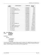
Parameter
Description
9 = rate 3/4 Sequential
RSC_n
Specifies the outer block code rate; 0 = no block coding; 1 = DVB compliant rate 188/204; 2 = non-
DVB mode rate 187/204
An additional restriction exists on link tables beyond the above parameter limits. The receive symbol rate of the
receiver should be less than 256000 sps for optimal performance.
Symbol rate can be queried with the RR command and is calculated using the following formula:
Symbol Rate = (Data Rate) * (1/Viterbi or 1/Sequential) * (1/Reed-Solomon) * (1 for BPSK or
1/2 for QPSK)
where Data Rate = LTD data rate parameter.
LTE Link Table Enable
Syntax:
LTE n
LTE
?
This command is used to enable the link tables. A value of 1 for
n
enables the current link table and a value of 2
for
n
enables both link tables.
LTW Link Table Wait
Syntax:
LTW n
LTW
?
This command is used to specify the number of seconds that the DBR waits before switching link tables. This
value is only used when LTE is set to a value of 2. A value of 0 for
n
disables the LTW feature; values between 1
second and 14400 seconds (4 hours) are valid for
n
.
The LTW time value forces the acquisition algorithm to delay before switching from the link table specified before
beginning to ping-pong. After this wait time has expired, the acquisition algorithm resumes trying each link table,
one directly after the other, without any further delay time. The wait time is only applied one time in an LTA
acquisition.
The purpose of LTW is to allow the DBR to concentrate on the link table specified by LTA for a period of time. If
after that time period there has been no successful acquisition of the specified table, then the acquisition will
resume normal ping-pong method of LTE 2, where acquisition of both link tables is attempted. Especially in the
case where there are two RF signals that the DBR is allowed to access, it is important to inform the receiver
which signal should take priority.
LTW is not applied to an acquisition caused by the AQ command, the loss of received signal or cycling power.
LV LNB
Voltage
Syntax: LV
n
LV
?
The LNB Voltage can be disabled or adjusted to +13VDC, +14VDC, +18VDC, +19VDC. Most LNBs require
+18VDC although some only r13VDC. If a cable run is extremely long, it may be necessary to provide an
additional volt to compensate for the voltage loss.
A value of 0 for
n
disables the LNB voltage output. A value of 1 for
n
outputs an LNB voltage of +13V. A value of 2
for
n
outputs an LNB voltage of +14V. A value of 3 for
n
outputs an LNB voltage of +18V. A value of 4 for
n
outputs an LNB voltage of +19V.
The default value for LV is 0.
5-24
Tiernan DBR3000
Summary of Contents for DBR3000
Page 2: ...Overview Page 1 2 Tiernan DBR3000 ...
Page 6: ...Warranty Policy Page vi Tiernan DBR3000 ...
Page 10: ...Preface Page x Tiernan DBR3000 ...
Page 14: ...Safety Precautions Page xiv Tiernan DBR3000 ...
Page 64: ......
Page 73: ...Troubleshooting Figure C 1 Coax Cable and F Connector Assembly Tiernan DBR3000 Page B 5 ...