

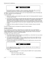


Maintenance and Troubleshooting
HM Hex
Mode
Syntax: HM
n
HM
?
HM
This command assigns the display format for the ST and FL commands to be decimal or hexadecimal. Valid
values for
n
are 0, hex mode disabled (display decimal format), or 1, hex mode enabled. A query displays the
current format.
ID
Receiver ID Query
Syntax: ID
?
This command displays the DBR ID serial number, which is used for individual unit addressing. The number
should be identical to the unit ID number as displayed on the label at the rear of the chassis.
IP IP
Address
Syntax: IP
address_nnn.nnn.nnn.nnn,mask_nnn.nnn.nnn.nnn,gateway_nnn.nnn.nnn.nnn
IP
?
IP
This command defines the IP address, subnet mask and default gateway of the receiver. The parameters are
required for any IP-based applications such as Telnet. The valid range for
address_nnn.nnn.nnn.nnn
and
gateway_nnn.nnn.nnn.nnn
is 0.0.0.0 to 223.255.255.255 with the exception of 127.0.0.0 to 127.255.255.255. The
valid range of
mask_nnn.nnn.nnn.nnn
is 0.0.0.0 to 255.255.255.255.
Note that an IP Address of 0.0.0.0 disables the Ethernet port.
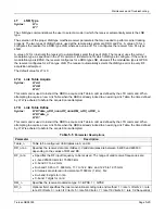
LA
Logical Address Definition
Syntax: LA
nn,address_nnnnn
LA
?
LA
This command allows the receiver to respond to logical addresses received over the network control channel. Up
to 32 logical addresses can be assigned to each receiver. The valid range for address_
nnnnn
is 1 to 16383. An
individual 0 for the address clears the logical address assignment. The receiver responds to all logical addresses
assigned and its unique physical address (unit ID).
The default value is No Logical Addresses Assigned.
Example:
The following command configures logical address 3 to 9312. The remote receiver will then act upon network
control messages addressed to unit 9312.
LA 3,9312
LO
Local Oscillator Offset
Syntax: LO
?
LO
The LO value represents the difference between the start acquisition frequency and the frequency where the
carrier was actually located. The LO value represents the sum of the offsets that are present at the receive site.
These offsets include the offset present in the LO of the LNB and the LO of the receiver. With a knowledge of the
actual offsets present at the receive site, the DBR can optimize its acquisition process.
5-22
Tiernan DBR3000
Summary of Contents for DBR3000
Page 2: ...Overview Page 1 2 Tiernan DBR3000 ...
Page 6: ...Warranty Policy Page vi Tiernan DBR3000 ...
Page 10: ...Preface Page x Tiernan DBR3000 ...
Page 14: ...Safety Precautions Page xiv Tiernan DBR3000 ...
Page 64: ......
Page 73: ...Troubleshooting Figure C 1 Coax Cable and F Connector Assembly Tiernan DBR3000 Page B 5 ...