


INSTALLATION
61
NC020 - Manual - 05 - 2022
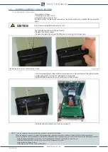
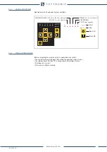
• Set the dip-switches on the top of the circuit board in accordance with the drawing shown below,.
• Move dip-switches according the following layout.
[1]
Note 1 Place switches 1 ... 4 according to the number on the printed circuit board (not considering the numbers on the component)
Dip-swithes position
Dip-switch localization concerning the nominal current setting inside the front board
Default settings:
- I
n
=5 A
- I
Nn
=5 A
Settings:
- I
n
=5 A
- I
Nn
=1 A
Settings:
- I
n
=1 A
- I
Nn
=1 A
Settings:
- I
n
=1 A
- I
Nn
=5 A
1 A
5 A
ON
IL
1
IL
3
IL
2
IN
1 A
5 A
ON
IL
1
IL
3
IL
2
IN
1 A
5 A
ON
IL
1
IL
3
IL
2
IN
1 A
5 A
ON
IL
1
IL
3
IL
2
IN
1
2
3
4
1
2
3
4
1
2
3
4
1
2
3
4


