background image


Introduction 

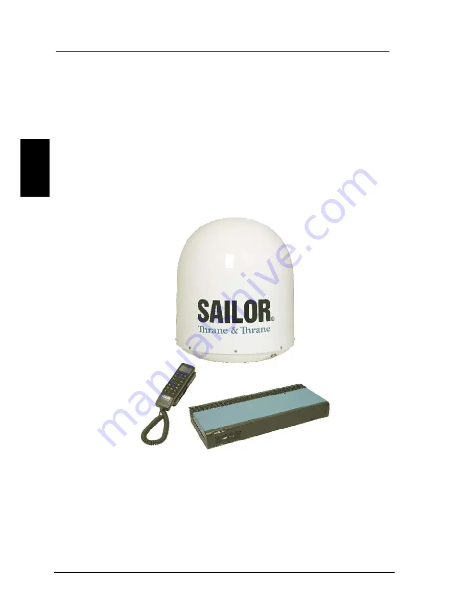
The SAILOR Fleet55 system 

2


2.4  The SAILOR Fleet55 system 

The SAILOR Fleet55 System includes the following system 
components: 

• 

TT-3008F SAILOR Fleet55 Antenna (ADU) 

• 

TT-3038C SAILOR Fleet55 Electronics Unit (BDU) 

• 

TT-3622C SAILOR Fleet Cradle without Distress 

• 

TT-3620F SAILOR Fleet Control Handset (4 wire) 

Accessories (manual, software, etc.) 


Instructions on how to assemble the system, wiring and 
specification, can be found in the Installation Manual. 

12 

May 2005 

Summary of Contents for TT-3084A Sailor Fleet77

Page 1: ...Thrane Thrane A S SAILOR Fleet77 TT 3084A SAILOR Fleet55 TT 3086A User Manual Copyright Thrane Thrane A S ALL RIGHTS RESERVED...

Page 2: ...ne A S It is recommended to download the latest version of the manual from the Thrane Extra net or request this from the distributor 2005 Thrane Thrane A S All rights reserved Printed in Denmark Trade...

Page 3: ...requirements Microwave Radiation Hazards During transmission the antenna in this system radiates Microwave Power This radiation may be hazardous if exposed directly to humans close to the antenna Dur...

Page 4: ...covers Component replacement and internal adjustment must be made by qualified maintenance personnel Do not replace components with the power cable connected Under certain conditions dangerous voltage...

Page 5: ...5 NMEA 0183 2000 interface 19 2 5 6 Discrete I O interface 20 2 5 7 USB Interface 20 2 5 8 Ethernet Interface 21 2 5 9 Power Connector 21 2 6 The Handset 22 2 6 1 LCD LED 23 2 6 2 Function Buttons 26...

Page 6: ...2 Call functions 59 4 2 1 Call using phone book 59 4 2 2 Call from handset connected to RJ11 60 4 2 3 Call from an ISDN phone 60 4 2 4 Fax call 61 4 2 5 Priority calls 62 4 2 6 Internal calls 63 4 3 S...

Page 7: ...5 1 1 The Map 94 5 1 2 Pin Codes 95 5 1 3 Phonebook 96 5 1 4 Satellite Setup 97 5 1 5 Routing 98 5 1 6 Setting up Time and Date 99 5 1 7 Barring Services 100 5 1 8 Settings 101 5 1 9 Antenna 102 5 2...

Page 8: ...Table of Contents 7 Index 151 Appendix A Menu Tree 153 iv May 2005...

Page 9: ...the SAILOR Fleet77 optionally supports 128 kbit s data service This manual has the following chapters Chapter 2 Introduction an overview of the Inmarsat Fleet system and its services Chapter 3 Gettin...

Page 10: ......

Page 11: ...Region ISP Inmarsat Service Provider LCD Liquid Crystal Display LED Light Emitting Diode LES Land Earth Stations MES Mobile Earth Station MMI Man Machine Interface MPDS Mobile Packet Data Service MSN...

Page 12: ...Introduction Abbreviations 2 T T Thrane Thrane A S TNID Terrestrial Network ID UDI Unrestricted Digital Information USB Universal Serial Bus 4 May 2005...

Page 13: ...the earth between approximately 70 N and 70 S The 4 Geo Stationary Inmarsat Satellites The satellites are your connection to the worldwide networks and they are managed by the Network Co ordination S...

Page 14: ...ata1 64 kbit s data 56 kbit s data Speech 3 1 kHz audio MPDS Low speed services mini M voice 9 6 kbit fax For a detailed description of each service see the last section of this chapter The above ment...

Page 15: ...al the IMN number in addition to the international access code for Inmarsat e g 870 600 555 555 Making calls from an Inmarsat Fleet terminal corresponds to making international calls as the country co...

Page 16: ...ff depends on the amount of data sent and received This service is a more cost effective solution for web browsing and other applications where there is no need for constant transmission of data in bo...

Page 17: ...components TT 3008C SAILOR Fleet77 Antenna ADU TT 3038C SAILOR Fleet77 Electronics Unit BDU TT 3622B SAILOR Fleet77 Distress Cradle TT 3620F SAILOR Fleet Control Handset 4 wire Accessories manual soft...

Page 18: ...gh gain antenna The antenna has built in all functions for satellite tracking including a GPS system TT 3038C 128 SAILOR Fleet77 Electronics Unit BDU All connectors for external equipment are placed o...

Page 19: ...ke telephone calls Furthermore it can be used to configure the system For a detailed description of the handset see section 2 6 The Cradle has a distress button a stop button and three LED s The distr...

Page 20: ...onents TT 3008F SAILOR Fleet55 Antenna ADU TT 3038C SAILOR Fleet55 Electronics Unit BDU TT 3622C SAILOR Fleet Cradle without Distress TT 3620F SAILOR Fleet Control Handset 4 wire Accessories manual so...

Page 21: ...ove Deck Unit is a stabilized high gain antenna The antenna has built in all functions for satellite tracking including a GPS system TT 3038C SAILOR Fleet55 77 Electronics Unit BDU All connectors for...

Page 22: ...essary data to recover the system after a replacement of the BDU TT 3622C SAILOR Fleet Cradle without Distress TT 3620F SAILOR Fleet Control Handset 4 wire The Handset is primary used to make telephon...

Page 23: ...andset 1 X4 Handset 2 X5 For future use ISDN Integrated Services Digital Network X7 USB Universal Serial Bus X8 Ethernet X9 Serial connector 1 X10 NMEA 0183 2000 X11 For future use 4 Discrete I O X12...

Page 24: ...d it can be used to make or receive phone calls utilizing one of the following services Cradle Handset Speech 3 1 kHz audio mini M voice Distress call Note At present only one port X4 is operational 2...

Page 25: ...conferencing equipment STE secure voice etc On F55 only one B channel 1 x 64 kbit s Data and one D channel control is used The F77 optionally supports two B channels 2 x 64 kbit s Data In order to ena...

Page 26: ...MSN Multiple Subscriber Number Depending on the brand of equipment it may be possible to program the equipment with more MSN s If a device should respond to a certain IMN number it must be programmed...

Page 27: ...PDS service Configuration of the terminal via FleetCP software See section 5 1 Connection of a IP Router 64 kbit s UDI using RS 232 When using the FleetCP program the PC must be connected to the RS 23...

Page 28: ...containing 4 configurable input output Note Interface is currently not supported Discrete I O 2 5 7 USB Interface USB Universal Serial Bus is an interface that allows a single universal plug to conne...

Page 29: ...5 8 Ethernet Interface The Ethernet interface is a RJ45 connector It can be used for the MPDS service Connect a computer through a switch or hub or connect directly using a crossover cable Ethernet R...

Page 30: ...is the Liquid Crystal Display LCD and Light Emitting Diodes LED section This section gives the user visual indications about the operation and status of the system 2 The second is the Function button...

Page 31: ...r It can be adjusted for contrast and is backlit for viewing in dimly lit areas or night operations The LCD display is graphically shown below IOR LESNAME Ready Te Are xt a Scroll n Secondary Function...

Page 32: ...REEN The Power LED indicates that the system has power ALARM LED RED The Alarm LED will illuminate when the system detects a fault If the LED is lit the error can be examined in the Alarm log See sect...

Page 33: ...n predefined values by means of the and keys The speaker The user can turn the external speaker on and off by pressing The symbol is displayed in the LCD when on Short message stored at a LES see sect...

Page 34: ...stem of the transceiver and change various settings Each button is described in detail below Symbol Meaning Enter the top level of the menu system See section 4 1 Menu System The button can also be us...

Page 35: ...reen display pressing OK will enter the menu system While in the menus pressing OK will enter the selected menu When entering data such as phone numbers or PIN codes pressing OK will accept the entry...

Page 36: ...on off This feature also includes toggling displaying of the short codes on off These codes can be used as shortcut to a given menu item by pressing the short code number using the numeric keys The 2...

Page 37: ...s C No signal strength in the display Pressing returns to the previous state Sets the brightness of the LED s See section 4 3 16 below LED Dimm Short cut to the Help desk menu See section 4 1 5 below...

Page 38: ...can be used to select between subsets of the alphabet and certain special characters by pressing the key a number of times until the wanted letter character is shown on the display To insert the lett...

Page 39: ...The Handset Introduction 2 D E F 3 G H I 4 J K L 5 M N O 6 P Q R S 7 T U V 8 W X Y Z 9 Move cursor forced space May 2005 31...

Page 40: ...side of the cradle Press to toggle the speaker on off The cradle includes 3 LED s ant two buttons Distress button The Distress button protected by plastic glass is used to initiate a Distress call See...

Page 41: ...Distress Cradle Introduction 2 Priority calls Distress Test LED Is lit when a distress test is performed See section 4 3 18 Distress Test May 2005 33...

Page 42: ......

Page 43: ...ke a call 3 1 1 How to power on the system The system can be powered on from the BDU or from the handset Power on from Handset The handset power button is placed in the upper left corner of the handse...

Page 44: ...laced on the back panel of the BDU See figure below Press and hold the power button for a few seconds or until the green LED on the front of the terminal lights up The display and all LED s on the han...

Page 45: ...ng The system may stay in the Wait for GPS state for an extended period if e g the antenna has been turned off for a long time or there is not a free view to the GPS satellites The time to get the GPS...

Page 46: ...m just press and hold the button After a few seconds the LCD display starts a count down to zero When the countdown is finished the display shows the message Release Power Button When the button is re...

Page 47: ...a Super User or a Service User Super User PIN The Super User has the same rights as the Normal User In addition the Super User can access the Super User menu See section 4 3 for details A Super User w...

Page 48: ...e system uses a service type mini M voice Speech or 3 1 kHz audio The service type used for a call from the handset is the service type configured as default for this handset and the LES operator used...

Page 49: ...erminal is similar to making international calls The specific IMN number a terminal may have more numbers as different services exist and more devices may be connected to the different hardware interf...

Page 50: ...of 1 second and the cradle buzzer will beep with the same interval After 5 seconds the button light will become constant and the buzzer will stop beeping Any ongoing calls will be pre empted unless i...

Page 51: ...TRESS Calling The call will be connected to the RCC the handset will display DISTRESS Connected and the cradle LED Priority call will light up The user can now talk to the RCC operator The Distress bu...

Page 52: ...area with Spot Beam coverage On Fleet77 systems the service is available in global beam Mobile Packet Data Service MPDS is a service that allows the mobile user to remain always connected to the Inter...

Page 53: ...service In case of an incoming call during an MPDS session with the Call Waiting Notification enabled the user has three options 1 The user can reject the pre emption of the MPDS connection by pressin...

Page 54: ...lease note The ISDN service is only available on Fleet55 systems when the vessel is positioned inside an area with Spot Beam coverage On Fleet77 systems the services are available in global beam The I...

Page 55: ...ls or the ability to lay down one of the B channels dynamically For fixed originated calls the terrestrial user is expected to dial the same INM number twice for each of the 64kbit s calls Please refe...

Page 56: ......

Page 57: ...e reached by pressing and a number corresponding to the entry level e g pressing will access the Alarm Log menu Pressing in the menu system will toggle shortcut numbers on and off The level of access...

Page 58: ...es call prefix for automatic calls and international access code The telephone number can hold up to 22 digits The name can hold from 0 to 16 characters The short code can be used for quick access whe...

Page 59: ...all For more information on how to make priority calls see section 4 2 5 Priority calls Inserting an entry in the phone book from within the phone book menu is done in the following example In this ex...

Page 60: ...tic Indian Pacific Spare1 Spare2 Spare3 Spare4 None Automatic W Atlantic E Atlantic Indian Pacific Spare 1 Spare 2 Spare 3 Spare 4 The selected area is marked with an If Automatic is selected the term...

Page 61: ...be the first LES tried next time the terminal is logged on Use to select The Area selected in section 4 1 2 Area will decide which LES s will be available for selection See section 4 3 25 LES Config f...

Page 62: ...comes operational a message is sent indicating that the LES operator has recorded a short message for the terminal The symbol in the handset display indicates the presence of such messages Each messag...

Page 63: ...t centers Editing inserting and deleting entries is done in exactly the same way as with the phone book but it can only be done from the super user menu Each entry contains a phone number name of the...

Page 64: ...t of the Alarm name indicates that the alarm is still active Select an alarm for viewing by pressing Each entry for an alarm contains an alarm description and the time and date when the alarm occurred...

Page 65: ...n Antenna GPS C No Choosing C No will display the signal strength in dBHz Pressing will return to the previous state Transceiver Release date Software release date Unit Type Type of unit Serial No T T...

Page 66: ...ORW AORE POR or IOR NSR state Not initialized initializing or initialized Type Mini M or NG Bulletin page 1 6 Page 1 to 255 or Invalid Spot beam ID Spot beam ID number between 1 255 SU CC Rxed Between...

Page 67: ...External GPS Not ready for future use 4 2 Call functions 4 2 1 Call using phone book The phone book can be used to initiate a call either by selecting an entry in the phone book and then pressing or o...

Page 68: ...ne in Denmark country code 45 is done by pressing the following keys on the phone When using one of the RJ11 analogue interfaces please make sure that the selected interface is configured for a servic...

Page 69: ...x calls can be made whether or not the fax has got a keypad Making calls from a fax with keypad connected to one of the three analogue RJ11 interfaces are done as international calls followed by Calli...

Page 70: ...l 0 Safety 1 Urgency 2 Distress 3 To make a Routine personal call via the Default LES press the number and initiate the call by pressing or To make a Routine personal Routine professional Safety or Ur...

Page 71: ...section 3 4 1 How to make a Distress call 4 2 6 Internal calls It is possible to make internal calls between any RJ11 2 wire interface The call is initiated by pressing the interface code in the tabl...

Page 72: ...got the following sub menus Call logs Routing Data Setup Contrast Logged Calls Total time Total MPDS Clear log Start time Phone number Duration OID Area LES acc code TNID CallPriority Received Transm...

Page 73: ...mulated call time since last reset Total MPDS shows the total accumulated number of bytes used in MPDS sessions The call log can be cleared by selecting the Clear Log menu Press to clear or to abort T...

Page 74: ...11 1 RJ11 2 RJ11 3 ISDN RS232 1 USB Ethernet Handset 1 RJ11 1 RJ11 2 RJ11 3 ISDN RS 232 1 USB Ethernet Note 1 The IMN number has to be defined before the service can be routed to an interface The serv...

Page 75: ...s If an IMN has an incoming route to an interface it is marked with If it has an outgoing route to an interface it is marked with a It is possible to change the routing status for each IMN to the opp...

Page 76: ...t s X Please note that MPDS can only be associated with RS 232 and Ethernet not the USB interface 4 3 3 Data setup This menu is used to setup baudrate and dataflow control for the two RS 232 interface...

Page 77: ...ontrast Call logs Routing Data setup Contrast Contrast 4 Press to Adjust The display contrast of the two handset can be adjusted To change the contrast level select the Contrast menu and adjust the va...

Page 78: ...tone and the handset volume Adjustable values are Ring Volume Off 1 2 3 4 default is 4 Ring Cadence 1 2 3 4 5 6 7 default is 1 Both settings are adjusted with and 4 3 6 Key Beep Key beep Off Press to...

Page 79: ...k is set to a non UTC time a clock error message will appear after a while By pressing the GPS time is automatically transferred Edit time 17 29 Ring Setup Key Beep Set UTC Time Set UTC Date Disclose...

Page 80: ...Current status is marked with a Note Disabling automatic reporting of position means that the terminal will report spot beam ID instead Note When a user initiate a maritime distress priority call the...

Page 81: ...gits in the mask matches the corresponding digits in the phone number starting from the first digit Press to insert a mask and to delete an entry Examples Mask 00453955 Valid number 004539558800 Valid...

Page 82: ...MPDS connecting 4 3 12 Ph Book Dial When this function is enabled Normal User will only be able to make calls using the phone book or the Help desk from a SAILOR handset Use and to scroll between Ena...

Page 83: ...e the prefix Prefix no 0045 Press to insert prefix Press to delete prefix Disclose Pos EA Allowed Dial BookDial Auto Prefix NM Ph 4 3 14 BarServiceIn All incoming calls on a specific service can be ba...

Page 84: ...ll through the services with Select the service with The service can then be set to Barred or Not barred with and Please note the 2x56 and 2x64 kbit s services are only visible if the 128 kbit s is en...

Page 85: ...Setup DistressTest Bright Dimm Off Press to Scroll Press to select 4 3 17 Antenna Setup The Ant Setup has got the following sub menus Reset ACU This function will reset the ACU in the antenna The DC p...

Page 86: ...eading of the ship is also needed but since the GPS does not supply the antenna with this information a relative angle of the antenna compared to the ships bow has to be known Select the antennas moun...

Page 87: ...o Scroll Press to select Enter the DistressTest menu and use and to enable distress test The display on the handset will show Distress Test Enabled and the Distress Test LED will start flashing The Di...

Page 88: ...Alarm Log Warning Log Clear log Audio Alarm On Off 4 3 19 Alarm log The Alarm Log logs all the alarms in the system From this menu the alarm can be viewed and cleared To clear the alarm list select t...

Page 89: ...as serious as alarms From this menu the warnings can be viewed and cleared To clear the warning list select the submenu Clear log and confirm the message Delete all by pressing Scroll through the war...

Page 90: ...d For a description of the pin codes see section 3 2 Use of PIN codes The PIN codes menu has the following sub menu SU PIN Chg The Super User PIN is changed here Type in the new PIN and press to accep...

Page 91: ...l again becomes operational a message is sent indicating that the LES operator has recorded a short message for the terminal The symbol in the handset display indicates the presence of such messages E...

Page 92: ...ensitivity As a consequence the output volume from the interfaces can be adjusted The volume can be set to High Medium or Low The setting is adjusted with and and selected with The default value is Hi...

Page 93: ...lowing sub menus Default LES PreferredLES Reset LES Distress LES Mail Box RJ11 Setup LES Config W Atlantic E Atlantic Pacific Indian Spare 1 Spare 2 Spare 3 Spare 4 001 Comsat 002 BT 003 KDD 004 Telen...

Page 94: ...and thus appears in the Default LES list above If all LES operators are allowed and can be used there are no markings As there are many operators you can use PreferredLES to make selections easier Th...

Page 95: ...ains two sub menus STU Setup Secure Telephone Unit and 128K Setup To enable the STU or 128K services a PIN code must be entered The PIN code can be retrieved from your distributor Use and to choose ST...

Page 96: ...t gets beyond the entered maximum value If set to OFF there will be no limits for the amount of data that can be transferred Use to select Limit and to manipulate To enter a maximum limit press Then u...

Page 97: ...general information about the Call Waiting Notification The first menu item is Support and it is used for enabling or disabling the Call Waiting Notification service A third option Dial Spec makes it...

Page 98: ...y be available in near future Choose the settings by pressing and press leave the menu The third menu item is Handset and it contains two sub items Notification and Ring Tone Notification can be eithe...

Page 99: ...er of seconds corresponding to the value of Pending Time If the user chooses to ignore the notification for a longer period the incoming call will be ignored Enter a value and press to save when leavi...

Page 100: ......

Page 101: ...rom the enclosed CD ROM The following pages contain a short introduction to FleetCP The picture below shows the initial screen when the program is started Connect the transceiver to PC using a standar...

Page 102: ...Phone Setup Antenna Setup General Status Alarm Status Call Log Antenna Alignment Debug Utilities and Terminal Window 5 1 1 The Map Clicking the map will show the Azimuth and Elevation to the satellit...

Page 103: ...ee picture below If a PIN is entered the lock will become unlocked and turn green At the same time a new logout button will appear next to the PIN code buttons Clicking this button resets the status o...

Page 104: ...nd right clicking in the phonebook area Entries here can be modified or deleted in the same way See picture below Further information can be found 4 1 1 Phonebook Inserting editing and deleting entrie...

Page 105: ...te Setup offers an easy way of setting up Allowed Preferred and default LES LES operators are dragged and dropped between the three tables Setup is made for each ocean region See picture below Read mo...

Page 106: ...correspond to service interface that is to be changed Click the or button in lower part of the screen to define it as a incoming or outgoing call To add a IMN click the New IMN ID button See picture...

Page 107: ...the time date or in the future the language use the MMI setup window Click the Use PC time button to import the time and date from the PC clock If the clock is set to a non UTC time a clock error mess...

Page 108: ...eetCP 5 1 7 Barring Services In the security window call restrictions can be enabled or disabled and an Auto prefix inserted See section 4 3 11 Allowed Dial 4 3 14 BarServiceIn and 4 3 15 BarServiceOu...

Page 109: ...CP PC programs 5 1 8 Settings In the Cradle Handset window it is possible to setup ring type ring volume LED brightness and display contrast RS 232 parameters of the terminal can be changed in the RS...

Page 110: ...meout number of allowed sky scans and the antennas mount position relative to the ships bow See section 4 3 17 Antenna Setup for details The antenna can be rebooted by clicking the Reset ACU button Th...

Page 111: ...232 The illustrations below shows typical hardware setup for a MPDS and ISDN data connection MPDS Hardware Connection For a MPDS session connect a RS 232 cable between the COM port of the computer an...

Page 112: ...ce This is done using the handset user interface The transceivers RS 232 configuration shall be using the handset user interface Baudrate 115200 baud Flow control Hardware Setting up your PC In this s...

Page 113: ...select Modems and add a Standard modem Do not let Windows detect the modem but manually choose a standard 28800 bps Modem Select the appropriate COM port i e the COM port that is connected to the term...

Page 114: ...ES XXX where XXX is the LES number If the terminal is to stay in MPDS mode with no activity for longer periods of time then the automatic disconnect when idle setting in Windows must be disabled Refer...

Page 115: ...programs Give the connection a recognizable name e g MPDS connection Include TCP IP as allowed network protocol and use default TCP IP settings Server assigned IP address Server assigned name server a...

Page 116: ...on can also be established manually In Windows open Dial Up networking and double click the appropriate icon Enter username and password if necessary Click Connect Wait for the connection to be comple...

Page 117: ...driver must be installed on the computer See the manufacturers installations guide for details on how to do this The terminal can be connected to ISDN equipment via an ISDN cable The equipment can be...

Page 118: ...le if the modem supports this interface Follow the modem manufacturers installation instructions for the appropriate operating system For this example a Lasat Unique 1280i ISDN modem was installed und...

Page 119: ...data equipment PC programs Step 2 Create a Dial up connection Open Dial up Networking from My computer Click Make new connection 5 Select the Lasat modem defined during step 1 as the dial up device Ma...

Page 120: ...vider Remember country code and area code if necessary Give the connection a recognizable name e g ISDN connection Include TCP IP as allowed network protocol and use TCP IP settings Server assigned IP...

Page 121: ...an also be established manually In Windows open Dial Up networking and double click the appropriate icon Enter username and password if necessary Click Connect Wait for the connection to be completed...

Page 122: ...alled This setup procedure is intended for PC s running a MS Windows operating system and the screen shots are from a Windows 2000 installation This section is divided into two steps Driver installati...

Page 123: ...sceiver to you PC using a standard USB cable A Found New Hardware window will appear shortly after 2 After a moment the Welcome to the Found New Hardware Wizard window appears 5 3 Click Next and the I...

Page 124: ...PC programs Set up of data equipment 4 Click Next and the Hardware Type window appears Choose Modems and click Next 5 116 May 2005...

Page 125: ...Set up of data equipment PC programs 5 The Install New Modem window appears Click Have Disk 6 Click Browse and choose the directory where you placed the drivers Then press OK 5 May 2005 117...

Page 126: ...PC programs Set up of data equipment 7 When the next screen appears press Next 5 8 Press Next 118 May 2005...

Page 127: ...Set up of data equipment PC programs 9 Press Yes 5 10 Press Finish to complete the driver installation May 2005 119...

Page 128: ...PC programs Set up of data equipment 11 Now open the Control Panel and double click on Phone and Modem Options 5 12 Select the Modem fan and choose Properties 120 May 2005...

Page 129: ...enter the initialization string AT WS45 6 and press OK Step 2 Create a Dial up connection 5 1 Make a new connection by selecting Start Settings Network and Dial up Connections Make New Connection A W...

Page 130: ...PC programs Set up of data equipment 2 Click Next 5 3 Select Dial up to private network and click Next 122 May 2005...

Page 131: ...Set up of data equipment PC programs 4 Select Thrane Thrane Fleet USB and press Next 5 5 Enter the destination phone number i e Internet Service Provider and press next May 2005 123...

Page 132: ...PC programs Set up of data equipment 6 Choose connection availability and press Next 8 Enter a name for the dial up connection and press Finish The system will now connect using USB 5 124 May 2005...

Page 133: ...us PPPoE clients 5 3 1 Windows XP with Built in PPPoE Client Prerequisites The PC must have an Ethernet adapter and Windows XP installed and both must be operational There must be a network connection...

Page 134: ...using broadband connection requiring user name and password and click Next 6 Type a name for the connection e g MPDS via PPPoE and click Next 7 Select Anyone and click Next 8 Type a random user name a...

Page 135: ...Thrane distributor and works for both Macintosh and PC Prerequisites The computer must have a working Ethernet adapter Connect the transceiver to the computer through a switch or hub or connect direct...

Page 136: ...PC programs Set up using Ethernet PPPoE 3 Choose the installation directory and click Next to install The program will now be installed 5 4 When done click Finish to restart the computer 128 May 2005...

Page 137: ...uble click 6 Enter random user name and password and then click START The status field tells you how far you have reached in the connection process After a successful authentication the status of the...

Page 138: ......

Page 139: ...leet77 or SAILOR Fleet55 Please note that all Cause Codes are also described in the Inmarsat SDM System Definition Manual see also Inmarsat M SDM Module 1 paragraphs 4 6 13 and 4 6 14 The following fo...

Page 140: ...e identity of the mobile terminal to which the call will actually be routed that terminal has become busy and hence cannot be rung 1021 No User responded MES is clearing the call because appropriate o...

Page 141: ...s of being established because the MES user has initiated a call from a terminal which is authorized to automatically preempt an existing fixed originated call 1144 Reserved 1145 Preemption MES is pre...

Page 142: ...an 2 digits 11D3 Protocol error unspecified LES is clearing the call because the service address information received from the MES is a 2 digit address which is either undefined or which is currently...

Page 143: ...red MES time out Distress Test exceeded 120s 1281 Channel type not implemented MES is rejecting the call because the MES is not equipped to provide the specified service 1291 Requested circuit channel...

Page 144: ...tocol error Unspecified MES is clearing the call because the supplementary services interrogation ISU type B2H and or subscriber digits SSU type ADH messages have not been received by the MES within t...

Page 145: ...Scrambling Vector information received from the MES is invalid ie 0000H 6959H or 7FFFH 1351 MES is clearing the call because the MES currently has insufficient free memory in which to store the short...

Page 146: ...ed call setup because ISDN Channel Alert messages used to establish a subsequent 56 64 kbit s call multiplexed onto a single carrier have not been received from the MES following transmission of MES c...

Page 147: ...call because the data received from the MES in the authentication reply message type B6H has been declared invalid by the LES authentication process 15A5 Bearer capability not authorized LES is reject...

Page 148: ...ress information nor a Scrambling Vector message type 8DH has been received by the LES within the allowed time limit 15C5 Protocol error Unspecified LES is clearing the call because the complete credi...

Page 149: ...ish a subsequent 56 64 kbit s call multiplexed onto a single carrier 15D1 Message with unrecognized parameter discarded LES is rejecting the call because the Channel Assignment message received from t...

Page 150: ...LES is clearing the call because of a malfunction in the credit card validity checking database or in the communications links thereto 1791 LES is clearing the call because of a malfunction in the aut...

Page 151: ...ing unspecified NCS is rejecting or clearing the call for a reason which is not covered by any of the currently defined Cause events 18C1 Subscriber absent NCS is rejecting the call because no message...

Page 152: ...LES is clearing the call in fixed originated call setup because a subsequent 56 64 kbit s call request was not received from the terrestrial user TE calling party following establishment of a previou...

Page 153: ...t Ok Vtune Alarm Unanswered distress call received Unanswered urgency priority call received Distress LES not selected in all ocean regions One or more of the selected distress LESs are not operationa...

Page 154: ...Troubleshooting List of Error messages 6 NAR Corrupt NSR Corrupt SVR Corrupt 146 May 2005...

Page 155: ...eep Mode FEU Error To Follow FEU Status heat alarm FEU Status burst alarm FEU Status power alarm FEU Status reset FEU Version Mismatch Try Upload ACU Comm Failure ACU Reset Powered Down ACU Reset Slee...

Page 156: ...mory Error ACU EEPROM Memory Error FPGA Init Memory Error FPGA SW CRC Motor Error Azm Drive Motor Error Elv Drive Motor Error Azm Winding Motor Error Elv Winding Motor Error BSM Winding Motor Error FP...

Page 157: ...ror protocol SU Error Sys Info CRC Sensor Err Roll Incl Sensor Err Pitch Incl Sensor Err Roll Rate Sensor Err Pitch Rate Sensor Err Yaw Rate Ctrl Logic ACU Matrix Ctrl Logic RX2 Comm Ctrl Logic RX2 Au...

Page 158: ...or1 AutoTune RX2 Error2 RX2 RSSI lo RX2 Error2 RX2 RSSI hi UNKNOWN ERR pos Handset Alarms Handset COM Error 1 1 This error means that the communication between handset and BDU has stopped for some rea...

Page 159: ...uration module 10 14 Connectors 15 Contrast 69 101 Country code 7 Data Limits 88 Data setup 68 Dataflow 68 Date 71 99 Dial Up networking 106 108 113 Discrete I O 15 20 Display symbols 25 Distress butt...

Page 160: ...ng setup 70 101 Ringing tone 70 RJ1115 16 60 61 63 66 84 7 Routine personal 62 Routine professional 62 Routing 66 98 RS 232 15 19 66 68 101 103 Safety 62 Satellite 5 Secure Telephone Unit 87 Service U...

Page 161: ...og Status Super Service Scroll through phone book None Automatic W Atlantic E Atlantic Pacific Indian Spare 1 Spare 2 Spare 3 Spare 4 Avaible LES in the region View Scroll through help desk View Super...

Page 162: ...Speed UTC Time Internal External Rx Frequency Tx Frequency Freq offset Acc offset AGC Gain Tx level Lo1 Lo2 Lo3 Temperature Power Mode Bulletin Ocean Region NSR status Type Page 1 Issue Page 2 Issue P...

Page 163: ...de Result codes 115200 57600 38400 19200 9600 4800 2400 1200 Auto None Xon Xoff Hardware Enable Disable Enable Disable Contrast 1 2 3 4 5 6 7 8 Super User PIN Handset 1 RJ11 1 RJ11 2 RJ11 3 ISDN RS232...

Page 164: ...ase NMEA Setup allowed dial Allowed Dial Enable Disable Ph Book Dial Prefix no Auto Prefix BarServiceOut Barred Not barred Mini M Voice Speech 3 1 kHz Audio 64 kbit s 56 kbit s 9600 Fax F77 MPDS 2x56...

Page 165: ...eset ACU Set Time Out Num SkyScan Mount Position Upload FEU Ant Setup RJ11 Setup High Medium Low LED Dimm Bright Dimm Off Audio Alarm On Off Mail Box Volume PABX Warning log View log Clear log Help De...

Page 166: ...Distress LES Call Waiting W Atlantic E Atlantic Pacific Indian Spare 1 Spare 2 Spare 3 Spare 4 Comsat BT TeleNor etc Data Limits MPDS ISDN Limit ON OFF 000000 Kb Limit ON OFF 00 00 hh mm STU PIN _ 12...

Page 167: ...e Ok to reset Distress LES Calibration IQ calib IQ const Modulator Demodulator Perform IQ calibration IAmp QAmp IOff QOff Phase MO adjust Debug Power Downs FEU Uploads Number Reset Old Boot New Boot B...

Page 168: ......

Reviews: