S3FC405, S3FC473, S3FC520
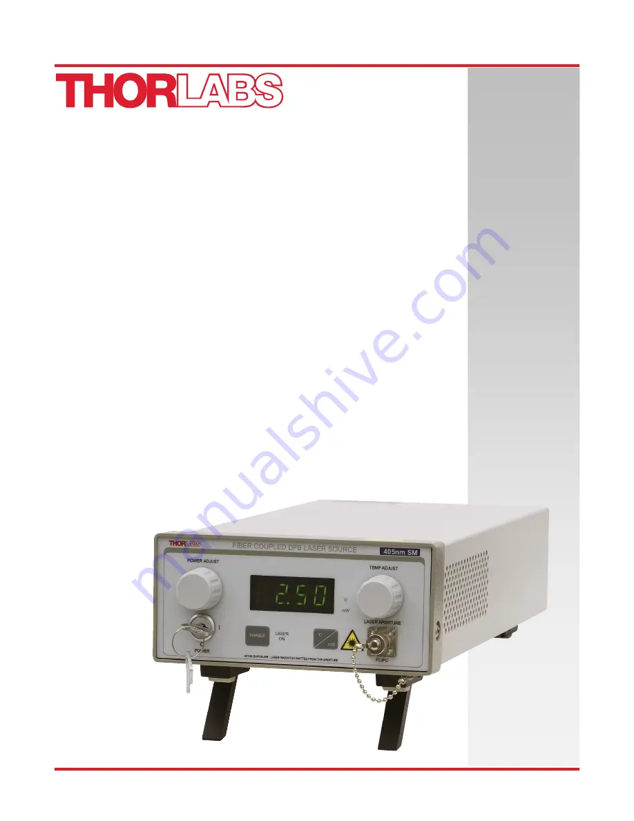
Fiber-Coupled Laser Source
User Guide
Page 1: ...S3FC405 S3FC473 S3FC520 Fiber Coupled Laser Source User Guide...
Page 2: ...2 Turning On the Source 7 5 3 Adjusting the Laser Output Power 7 5 4 Turning the Laser Off 7 5 5 Adjusting the Temperature of the Laser Diode 7 5 6 Modulating the Laser Output 8 Chapter 6 Making the...
Page 3: ...Description Direct Current Alternating Current Both Direct and Alternating Current Earth Ground Terminal Protective Conductor Terminal Frame or Chassis Terminal Equipotentiality On Supply Off Supply...
Page 4: ...a properly grounded power cable to power the unit Do not obstruct the air ventilation slots in the housing Make sure that the line voltage rating marked on the rear panel agrees with your local supply...
Page 5: ...ot temperature controlled version S3FC series comes equipped with a thermo electric cooler to stabilize the output wavelength and comes in three wavelengths 405 nm 473 nm and 520 nm The DFB versions c...
Page 6: ...ure 1 4 Using a flat blade screwdriver turn the Line Select Switch to the appropriate setting to match the AC input voltage you will be using 5 Remove the cover to the fuse holder You will find the fu...
Page 7: ...tch to the appropriate position and install the proper fuse 2 Locate the unit on a dry level working surface 3 Make sure the POWER key switch on the front of the unit is in the OFF position key perpen...
Page 8: ...er Cover should be installed on FC connector when fiber removed Display Select Switch Toggles the display between LD Power and temperature set point Keylock Power Switch Turn on power to the unit Key...
Page 9: ...e end of your fiber optic cable may be less depending on the quality of the connection NOTE Each unit is calibrated internally to limit the maximum operating power of the laser diode to a safe operati...
Page 10: ...is full counter clockwise the drive current is not zero but actually at the threshold current This should be kept in mind when using the modulation input 1 Connect a signal generator or 0 to 5 V power...
Page 11: ...orlabs are configured with a shorting device installed in the Interlock connector If you are not going to use this feature then you can leave the shorting device installed and the unit will operate no...
Page 12: ...the unit 7 2 Connector Cleaning Always clean the ferrule end of your fiber patch cable prior to inserting it into the output FC Adapter Your benchtop source comes with a fiber cleaning card FCC CLN4...
Page 13: ...mbient Display Accuracy 10 Setpoint Resolution 0 01 mW Adjustment Range 0 mW to Full Power TEC Stability 0 005 C 1 C Setpoint Accuracy 0 25 C Setpoint Resolution 0 1 C Adjustment Range 20 1 C to 30 1...
Page 14: ...Fiber Coupled Laser Source Chapter 9 Mechanical Drawing Page 12 19146 D02 Chapter 9 Mechanical Drawing Figure 6 Mechanical Drawing 12 49 317 3 mm 11 43 290 2 mm 2 59 65 7 mm 5 76 146 4 mm 3 06 77 8 mm...
Page 15: ...C Certifocate of Compliance Rev L June 5 2017 Page 13 Chapter 10 FCC EMC Certifocate of Compliance Emissions comply with the Class A Limits of FCC Code of Federal Regulations 47 Part 15 Subpart B1 1 U...
Page 16: ...orlabs products such as Pure OEM products that means assemblies to be built into a unit by the user e g OEM laser driver cards Components Mechanics and optics Left over parts of units disassembled by...
Page 17: ...ion USA Canada and South America Thorlabs Inc sales thorlabs com techsupport thorlabs com Europe Thorlabs GmbH europe thorlabs com France Thorlabs SAS sales fr thorlabs com Japan Thorlabs Japan Inc sa...
Page 18: ...www thorlabs com...