ODC001 Servo Motor Driver
2.6
Verifying Software Operation
2.6.1
Initial Setup
1) Install the APT software as detailed in Section 2.4.
2) Connect the driver to the DC motor actuator or the relevent axis of the associated
stage (see Section 2.3.).
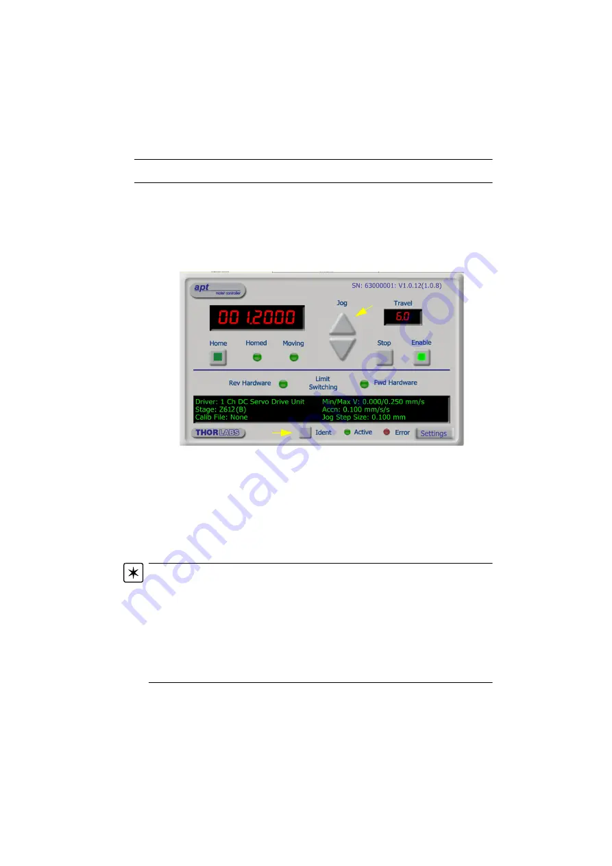
3) Run the APTUser utility and check that the Graphical User Interface (GUI) panel
appears and is active.
Fig. 2.7 Gui panel showing jog and ident buttons
4) Click the ‘Ident’ button. The LED on the front panel of the OptoDCDriver flashes.
This is useful in multi-channel systems for identifying which driver unit is
associated with which GUI.
5) Click the jog buttons on the GUI panel and check that the motor or axis connected
to the OptoDCDriver moves. The position display for the associated GUI should
increment and decrement accordingly.
Follow the tutorial steps described in Chapter 3 for further verification of operation.
Note. The ’APT Config’ utility can be used to set up simulated hardware configurations
and place the APT Server into simulator mode. In this way it is possible to create any
number and type of simulated (virtual) hardware units in order to emulate a set of real
hardware. This is a particularly useful feature, designed as an aid to application program
development and testing. Any number of ’virtual’ control units are combined to build a
model of the real system, which can then be used to test the application software offline.
If using real hardware, ensure that Simulator Mode is disabled. If using a simulated
setup, enable Simulator Mode and set up a ‘Simulated Configuration’ - see Section 4.8.
or the APTConfig helpfile for detailed instructions.


