background image

Cerna Mini Microscopes


Chapter 6: Specifications 

Rev. D, July 9, 2018 


Page 17


Stepper Motor Specifications 

Thread Screw Pitch 

0.3 mm 

Step Angle 

1.8° 

Limit Switches 

Hall Effect Sensors 

Phase Current 

0.49 A 

Phase Resistance 

5.1 

Ω 

Phase Inductance 

1.5 mH 

Insulation Resistance 

20 MΩ 


6.4 

Motion Controller  

Specification 

Value 

Item #


MCM3001 

Motor Output 

Motor Drive Voltage 

24 V 

Motor Drive Current 

7.0 A (Peak) 
3.0 A (RMS) 

Motor Drive Type 

12-Bit PWM Control 

Control Algorithm 

Open-Loop Microstepping 

Stepping 

64 Microsteps per Full Step 

Encoder Resolution 

0.212 µm 

Total Steps per Revolution 

12800 

Maximum Stepping Velocity 

4577 steps/s 

Position Feedback 

Quadrature Encode (QEP) Input, 5 V 

Encoder Feedback Bandwidth 

16 MHz 

Position Counter 

32-Bit 

Operating Modes 

Position and Velocity 

Velocity Profile 

Trapezoid 

Motor Drive Connector 

Mechanical Specifications 

15 Position D-Type, Micro-D Plug, Male Pin 

Connector 

Motor Drive Outputs 

200 

Quadrature Encoder (QEP) Input 

Single Ended 

Limit Switch Inputs 

Forward, Reverse, Index 

Encode Supply 

5 V 

Input Power Requirements 

Voltage 

24 VDC 

Current 

3.75 A (Peak) 

Summary of Contents for Cerna Series

Page 1: ...Cerna Mini Microscopes User Guide...

Page 2: ...Camera 14 Chapter 5 Maintaining the SFM Series 15 5 1 Cleaning 15 Chapter 6 Specifications 16 6 1 Microscope Body Specifications 16 6 2 Camera Port 16 6 3 Motorized XYZ Translation 16 6 4 Motion Contr...

Page 3: ...Cerna Mini Microscopes Chapter 8 Warranty 35 Chapter 9 Regulatory 36 Chapter 10 Thorlabs Worldwide Contacts 37...

Page 4: ...escription Direct Current Alternating Current Both Direct and Alternating Current Earth Ground Terminal Protective Conductor Terminal Frame or Chassis Terminal Equipotentiality On Supply Off Supply In...

Page 5: ...fer to the relevant User Guide of the individual product for safety instructions Please read the following warnings and cautions carefully before operating the unit WARNING DO NOT use the device for a...

Page 6: ...industry standard cameras The SFMGFP and SFMGFP2 microscopes each consist of a motorized microscope body a camera port a filter cube a light source an LED collimation module an objective a scientific...

Page 7: ...FP o Epi Illuminator Module for LED with 80 to 120 Divergence Angle o Blue LED for GFP Excitation 470 nm Nominal Wavelength 710 mW Typical Output Power at Max Current 25 nm FWHM Full Width at Half Max...

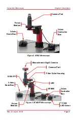
Page 8: ...age 5 Figure 2 SFM2 Microscope Figure 3 SFMGFP Microscope 3 Axis Controller Box 3 Axis Knob Box LED Filter Cube Housing N10X PF Camera Port SFM80 Monochrome Gig E Camera Focus Module T Cube LED Driver...

Page 9: ...croscopes Chapter 3 Description Page 6 TTN109666 D02 Figure 4 SFMGFP2 Microscope 3 Axis Controller Box 3 Axis Knob Box LED Filter Cube Housing N10X PF Camera Port SFM80 Focus Module T Cube LED Driver...

Page 10: ...Module SFM2 Cerna Mini Microscope SFMGFP Cerna Mini Microscope with Epi Illuminator Module for GFP Alexa Fluor 488 with CCD Camera SFMGFP2 Cerna Mini Microscope with Epi Illuminator Module for GFP Al...

Page 11: ...2100M USB 1 80 Collimating Tube with XY Adjustment Item SFM80 1 1 Nikon Plan Fluorite Imaging Objective Item N10X PF 1 1 LED Blue 470 nm Item M470L3 1 1 OEM Microscopy Filter Cube Item MDFM MF2 1 1 M6...

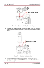
Page 12: ...ra Requirements The following additional accessories not included are required for installation of the microscope 1 5 mm Hex Key 2 mm Hex Key 2 5 mm Hex Key 5 64 Hex Key 4 3 1 Microscope 1 Use four SH...

Page 13: ...ex key to mount the Camera Port onto the Filter Cube Housing For SFM2 mount the Camera Port directly to the Dovetail Plate Figure 7 Mounting the Camera Port 5 Use two SHCS to mount the 3 Axis Controll...

Page 14: ...s from the Focus Module and PLS XY Stage to the 3 Axis Knob Box 7 Connect the cable from the 3 Axis Knob Box to the 3 Axis Controller Box 8 Connect the power supply from the 3 Axis Controller Box to a...

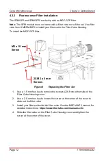
Page 15: ...ll the MDF GFP filter Figure 8 Replacing the Filter Set 1 Use a 1 5 mm hex key to remove the screws 2X from either side of the Filter Cube Housing cover 2 Use a 2 5 mm hex key to loosen the screw at t...

Page 16: ...he Filter Cube Housing included in the SFMGFP and SFMGFP2 configurations comes with a pre installed LED and SFM80 collimation tube 1 Use two SHCS to mount the T Cube LED Driver onto the optical table...

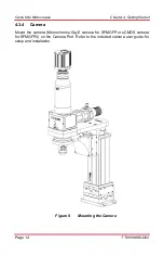
Page 17: ...g Started Page 14 TTN109666 D02 4 3 4 Camera Mount the camera Monochrome Gig E camera for SFMGFP or sCMOS camera for SFMGFP2 on the Camera Port Refer to the included camera user guide for setup and in...

Page 18: ...t office see Thorlabs Worldwide Contacts on page 37 for details for assistance from an applications engineer 5 1 Cleaning Refer to the relevant section in the User Guide of individual products for cle...

Page 19: ...ective Thread Adapter Included External M32 x 0 75 Threads Internal M25 x 0 75 Threads Optional Breadboard Not Included MB1224 or MB3060 M 6 2 Camera Port Specification Value Item WFA4100 Magnificatio...

Page 20: ...ol Control Algorithm Open Loop Microstepping Stepping 64 Microsteps per Full Step Encoder Resolution 0 212 m Total Steps per Revolution 12800 Maximum Stepping Velocity 4577 steps s Position Feedback Q...

Page 21: ...ength 6 6 LED Specifications SFMGFP SFMGFP2 Specification Value Item M470L3 Color Blue Nominal Wavelength 470 nm LED Power Output Min 650 mW LED Power Output Typical 710 mW Maximum Current CW 1000 mA...

Page 22: ...y Range 0 1 kHz Duty Cycle Range 20 80 1 kHz 2 98 100 Hz 0 2 99 8 10 Hz Modulation Form Square Wave PWM Logic Input Levels TTL Min H Level 2 V Max L Level 0 55 V Slew Rate 18 mA s Rise Time 51 s Decay...

Page 23: ...ch Dig Substrate Fused Silica Center Wavelength 469 nm 525 nm FWHM 35 nm 39 nm Reflection Band Ravg 90 452 490 nm Transmission Band Tabs 90 505 800 nm AR Coating3 Rabs 2 400 800 nm 6 9 Objective Speci...

Page 24: ...Converter Gain 0 to 1023 Steps 0 036 dB Step Optical Black Clamp 0 to 1023 Steps 0 25 ADU Step 7 Vertical Hardware Binning8 Continuous Integer Values from 1 to 24 Horizontal Software Binning8 Continu...

Page 25: ...1 Slot Connectivity USB or Internet Connectivity for Driver Installation Example Frame Rates at 1 ms Exposure Time Data Rate13 20 MHz 40 MHz Full Sensor 1392 x 1040 12 fps 23 fps Full Sensor Bin by 2...

Page 26: ...Cerna Mini Microscopes Chapter 6 Specifications Rev D July 9 2018 Page 23 Figure 11 Quantum Efficiency of 1501M GE Camera...

Page 27: ...Cerna Mini Microscopes Chapter 6 Specifications Page 24 TTN109666 D02 Figure 12 IR Blocking Filter Transmission of 1501M GE Camera...

Page 28: ...16 Region of Interest ROI 8 x 2 Pixels16 to 1920 x 1080 Pixels Rectangular Read Noise 1 e Median17 Digital Output 16 Bit Dynamic Range Up to 87 dB Full Well 23 ke Lens Mount C Mount 1 000 32 USB Power...

Page 29: ...er Installation Example Frame Rates at 1 ms Exposure Time Data Rate21 30 fps 50 fps Full Sensor 1920 x 1080 30 fps 50 fps Half Sensor 960 x 540 60 fps 100 fps 1 10 Sensor 192 x 108 300 fps 500 fps Fig...

Page 30: ...Cerna Mini Microscopes Chapter 7 Mechanical Drawings Rev D July 9 2018 Page 27 Chapter 7 Mechanical Drawings Figure 14 Mechanical Drawing of SFM Module Side Front and Back View...

Page 31: ...Cerna Mini Microscopes Chapter 7 Mechanical Drawings Page 28 TTN109666 D02 Figure 15 Mechanical Drawing of SFM Module Top and Bottom View...

Page 32: ...Cerna Mini Microscopes Chapter 7 Mechanical Drawings Rev D July 9 2018 Page 29 Figure 16 Mechanical Drawing of SFM2 Module Side Front and Back View...

Page 33: ...Cerna Mini Microscopes Chapter 7 Mechanical Drawings Page 30 TTN109666 D02 Figure 17 Mechanical Drawing of SFM2 Module Top and Bottom View...

Page 34: ...Cerna Mini Microscopes Chapter 7 Mechanical Drawings Rev D July 9 2018 Page 31 Figure 18 Mechanical Drawing of SFMGFP Module Side Front and Back View...

Page 35: ...Cerna Mini Microscopes Chapter 7 Mechanical Drawings Page 32 TTN109666 D02 Figure 19 Mechanical Drawing of SFMGFP Module Top and Bottom View...

Page 36: ...Cerna Mini Microscopes Chapter 7 Mechanical Drawings Rev D July 9 2018 Page 33 Figure 20 Mechanical Drawing of SFMGFP2 Module Side Front and Back View...

Page 37: ...Cerna Mini Microscopes Chapter 7 Mechanical Drawings Page 34 TTN109666 D02 Figure 21 Mechanical Drawing of SFMGFP2 Module Top and Bottom View...

Page 38: ...Chapter 8 Warranty Thorlabs warrants that all products sold by Thorlabs will conform to the published specifications and shall be free from defects in material and workmanship under normal use handli...

Page 39: ...rlabs products such as Pure OEM products that means assemblies to be built into a unit by the user e g OEM laser driver cards Components Mechanics and optics Left over parts of units disassembled by t...

Page 40: ...rlabs de Email europe thorlabs com Scandinavia Thorlabs Sweden AB Bergfotsgatan 7 431 35 M lndal Sweden Tel 46 31 733 30 00 Fax 46 31 703 40 45 www thorlabs com Email scandinavia thorlabs com France T...

Page 41: ...www thorlabs com...

Reviews: