


E L E C T R I C A L S Y S T E M
T H O R M O T O R C O A C H | M A D E T O F I T
73
10
Unless you intend to run the vehicle engine, keep the
ignition switch in the OFF position. Doing so will:
• Reduce the risk of unnecessary chassis battery
drain.
• Allows the battery isolation relay to connect the
auxiliary battery to the house charging system.
CAUTION
CAUTION
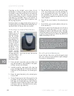
Typical emergency start
switch
It is strongly advised to turn off all 12 volt DC devices
before using the emergency start feature. This will help
ensure that all available energy stored in the auxiliary
battery(ies) can be used for vehicle starting.
NOTICE
NOTICE
Battery Isolation Relay
When the motorhome’s engine is not running, the chassis
and auxiliary battery(ies) are electrically isolated by the
use of a battery isolation relay. This device prevents house
power consumption from discharging the chassis battery
while the motorhome is parked.
ADDITIONAL CHARACTERISTICS OF THE
BATTERY ISOLATION RELAY:
1. The battery isolation relay electrically delays con-
necting the auxiliary batteries to the vehicle charging
system for approximately 15 seconds; this allows the
alternator time to reach full charging ability.
2. After this initial time delay, the battery isolation relay
senses the voltage of the vehicle charging system. The
isolator connects the auxiliary battery to the vehicle’s
charging system only when the chassis charging sys-
tem reaches the correct voltage.
3. If the vehicle’s charging voltage drops below 13.2 volts
for a period of 4 seconds, due to low idle speed and/or
excessive load, the battery isolation relay will discon-
nect the auxiliary batteries from the vehicle’s charging
system until the vehicle’s charging voltage returns to
a level of 13.2 volts or above. For this feature, there is
a built-in delay period of approximately 10 seconds.
4. The battery isolation relay allows vehicle starting
from the auxiliary battery(ies) via the Emergency
(Auxiliary) Start Switch.
Emergency (Auxiliary) Start Switch
(if equipped)
Your motorhome may be equipped with an Emergency
(auxiliary or AUX) Start Switch. Located in the vehicle’s
cockpit, near the drivers seating area, this switch connects
the auxiliary battery(ies) to the vehicle’s starting circuit.
This feature is used for situations when the chassis battery
is too depleted to start the vehicle on its own. Connecting
the auxiliary battery(ies) to the engine starting circuit
may provide the needed energy to start the motorhome’s
engine. When the Emergency Start Switch is released, the
auxiliary battery(ies) are removed from the engine starting
circuit.
TO OPERATE:
1. Depress the ‘EMER START’
switch, located on the front
driver’s dash and HOLD.
2. Use the ignition switch (key
or start button) to start chas-
sis engine.
3. Release the ‘EMER START’
switch after the engine has
started.
NOTE:
• When using the Emergency Start feature, do not
hold the ignition key in the start position for more
than 30 seconds.
• Be careful not to run down the auxiliary battery as
this could leave you without 12 volts DC power.
• Emergency Start is not available on Sprinter-based
motorhomes.
Summary of Contents for CLASS A
Page 1: ...OWNER S MAN UAL CLASS A AND CLASS C MOTORHOMES ...
Page 2: ......
Page 12: ...C U S T O M E R C A R E 8 7 7 8 5 5 2 8 6 7 This page is intentionally left blank 4 ...
Page 18: ...C U S T O M E R C A R E 8 7 7 8 5 5 2 8 6 7 This page is intentionally left blank 10 ...
Page 36: ...C U S T O M E R C A R E 8 7 7 8 5 5 2 8 6 7 This page is intentionally left blank 28 ...
Page 46: ...C U S T O M E R C A R E 8 7 7 8 5 5 2 8 6 7 This page is intentionally left blank 38 ...
Page 58: ...C U S T O M E R C A R E 8 7 7 8 5 5 2 8 6 7 This page is intentionally left blank 50 ...
Page 64: ...C U S T O M E R C A R E 8 7 7 8 5 5 2 8 6 7 This page is intentionally left blank 56 ...
Page 74: ...C U S T O M E R C A R E 8 7 7 8 5 5 2 8 6 7 This page is intentionally left blank 66 ...
Page 108: ...C U S T O M E R C A R E 8 7 7 8 5 5 2 8 6 7 This page is intentionally left blank 100 ...
Page 118: ...C U S T O M E R C A R E 8 7 7 8 5 5 2 8 6 7 This page is intentionally left blank 110 ...
Page 122: ...C U S T O M E R C A R E 8 7 7 8 5 5 2 8 6 7 This page is intentionally left blank 114 ...
Page 123: ......
Page 124: ...thormotorcoach com TMC Part Number 0454934 Rev Date 10 01 2020 ...


