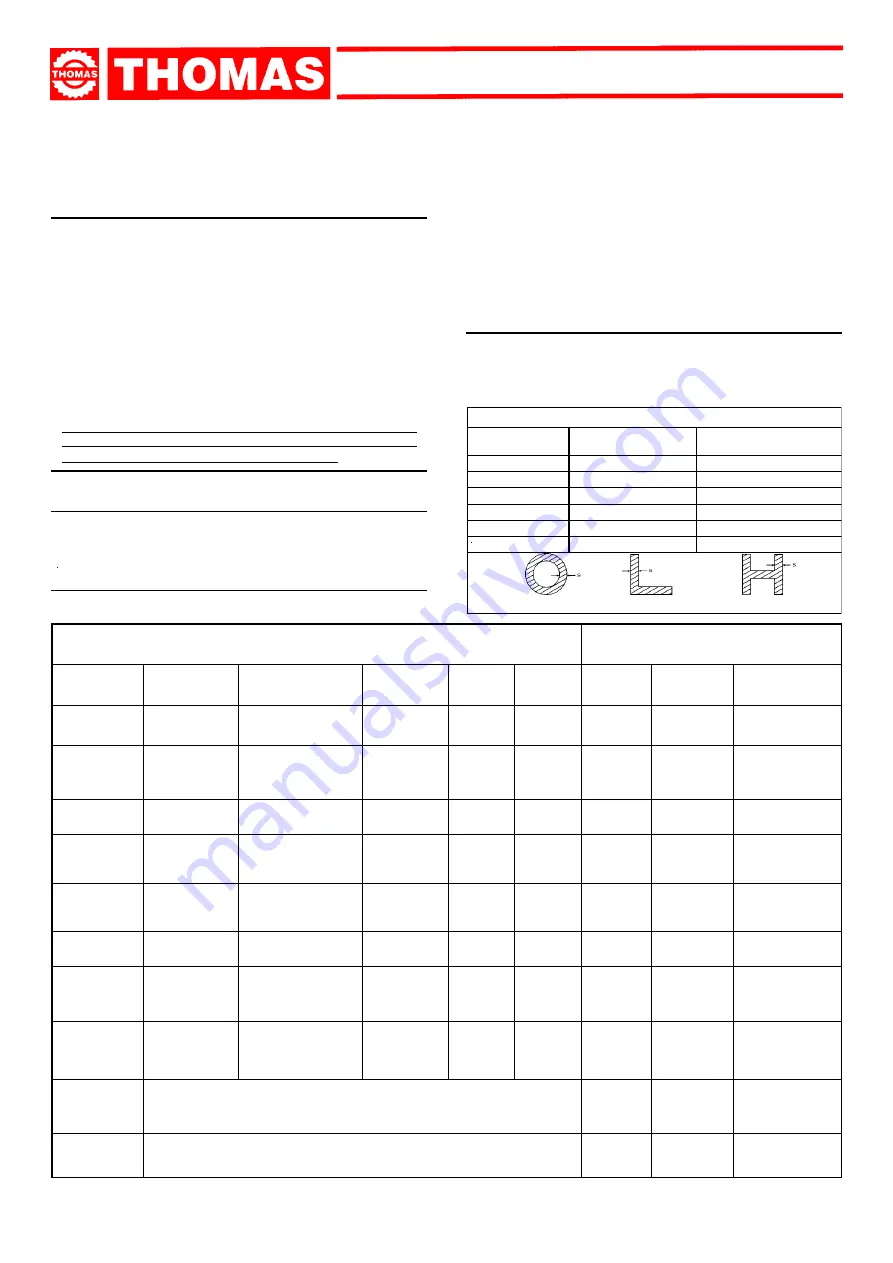
Thomas SAR 460 SA G DIGIT Use And Maintenance Manual Download Page 16

16

 SAR 460 SA G

TYPES OF STEEL

CHARACTERISTICS

USE

I

UNI

D

DIN

F

AF NOR

GB

SB

USA

AISI-SAE

Hardness

BRINELL

HB

Hardness

ROCKWELL

HRB

R=N/mm²

Construction

steels

Fe360
Fe430
Fe510

St37
St44
St52

E24
E28
E36

----

43
50

----
----
----

116
148
180

67
80
88

360÷480
430÷560
510÷660

Carbon

steels

C20
C40
C50
C60

CK20
CK40
CK50
CK60

XC20

XC42H1

----

XC55

060 A 20
060 A 40

----

060 A 62

1020
1040
1050
1060

198
198
202
202

93
93
94
94

540÷690
700÷840
760÷900
830÷980

Spring

steels

50CrV4

60SiCr8

50CrV4

60SiCr7

50CV4

----

735 A 50

----

6150
9262

207
224

95
98

1140÷1330
1220÷1400

Alloyed steels for

hardening and

tempering and for

nitriding

35CrMo4

39NiCrMo4
41CrAlMo7

34CrMo4

36CrNiMo4
41CrAlMo7

35CD4

39NCD4

40CADG12

708 A 37

----

905 M 39

4135
9840

----

220
228
232

98
99

100

780÷930

880÷1080
930÷1130

Alloyed

casehardening

steels

18NiCrMo7

20NiCrMo2

----

21NiCrMo2

20NCD7

20NCD2

En 325

805 H 20

4320

4315

232

224

100

98

760÷1030

690÷980

Alloyed for

bearings

100Cr6

100Cr6

100C6

534 A 99

52100

207

95

690÷980

Tool steel

52NiCrMoKU

C100KU

X210Cr13KU

58SiMo8KU

56NiCrMoV7C100K

C100W1

X210Cr12

----

----
----

Z200C12

Y60SC7

----

BS 1

BD2-BD3

----

----

S-1

D6-D3

S5

244
212
252
244

102

96

103
102

800÷1030

710÷980

820÷1060
800÷1030

Stainless

steels

X12Cr13

X5CrNi1810
X8CrNi1910

X8CrNiMo1713

4001
4301

----

4401

----

Z5CN18.09

----

Z6CDN17.12

----

304 C 12

----

316 S 16

410
304

----

316

202
202
202
202

94
94
94
94

670÷885
590÷685
540÷685
490÷685

Copper alloys

Special brass

Bronze

 Aluminium copper alloy G-CuAl11Fe4Ni4 UNI 5275
 Special manganese/silicon brass G-CuZn36Si1Pb1 UNI5038
 Manganese bronze SAE43 - SAE430
 Phosphor bronze G-CuSn12 UNI 7013/2a

220
140
120
100

98
77
69

56,5

620÷685
375÷440
320÷410
265÷314

Cast iron

 Gray pig iron                         G25
 Spheroidal graphite cast iron GS600
 Malleable cast iron                 W40-05

212
232
222

96

100

98

245
600
420

MATERIAL
CLASSIFICATION AND
CHOICE OF TOOL

9

Since the aim is to obtain excellent cutting quality, the vari-
ous parameters such as hardness of the material, shape
and thickness, transverse cutting section
 of the part to be
cut, selection of the type of cutting blade, cutting speed
and  control of saw frame lowering.These specifications
must therefore be harmoniously combined in a single oper-
ating condition according to practical considerations and
common sense, so as to achieve an optimum condition that
does not require countless operations to prepare the ma-
chine when there are many variations in the job to be
performed.The various problems that crop up from time to
time will be solved more easily if the operator has a good
knoledge of these specifications.
WE THEREFORE RECOMMEND YOU TO ALWAYS USE
GENUINE "THOMAS" SPARE BLADES THAT GUARANTEE
SUPERIOR QUALITY AND PERFORMANCE.

9.1 - Definition of materials

The table at the foot of the page lists the characteristics of the
materials to be cut, so as to choose the right tool to use.

9.2 - Selecting blade

First of all the pitch of the teeth must be chosen, in the other

BLADE TEETH SELECTION TABLE

THICKNESS MM

 Z CONTINUOUS

TOOTH DESIGN

Z COMBO

TOOTH DESIGN

TILL 1.5

14

10/14

FROM 1 TO 2

8

8/12

FROM 2 TO 3

6

6/10

FROM 3 TO 5

6

5/8

FROM 4 TO 6

6

4/6

MORE THAN 6

4

4/6

S = THICKNESS

words, the number of teeth per inch (25,4 mm) suitable for the
material to be cut, according to these criteria:
- parts with a thin and/or variable section such as profiles, pipes

and plate, need close toothing, so that the number of teeth
used simultaneously in cutting is from 3 to 6;

- parts with large transverse sections and solid sections need

widely spaced toothing to allow for the greater volume of the
shavings and better tooth penetration;

- parts made of soft material or plastic (light alloys, mild bronze,

teflon, wood, etc.) also require widely spaced toothing;

- pieces cut in bundles require combo tooth design.

9.3 - Teeth pitch

As already stated, this depends on the following factors:
- hardness of the material
- dimensions of the section
- thickness of the wall

Summary of Contents for SAR 460 SA G DIGIT

Page 1: ...60 SA G THOMAS S p A Via Pasubio 32 36033 Isola Vicentina VI Telefono 0444 97 61 05 Fax 0444 97 69 34 Registro Imprese n 4272 VI 116 REA n 93906 Vicenza SAR 460 SA G DIGIT USE AND MAINTENANCE MANUAL 2...

Page 2: ...ee TheCompanyguaranteesthatthemachine describedinthismanual hasbeendesignedtomeetsafetyrequirements Asformachinefunctionality inspectionhasbeen successful Themachineisguaranteedfor12months theguarante...

Page 3: ...asubio 32 36033 ISOLA VIC ITALIA SAR 460 SA G DIGIT Machine certification and identification marking MACHINE LABEL TYPE SERIAL NUMBER YEAROFMANUFACTURE Space reserved for the NAME and STAMP of the DEA...

Page 4: ...ays wear suitable eye protection Never put your hands or arms into the cutting area while the machine is operating Do not shift the machine while it is cutting Do not wear loose clothing with sleeves...

Page 5: ...metal building materials with different shapes and profiles used in workshops turner s shops and general mechanical structural work Only one operator is needed to use the machine that must stand as sh...

Page 6: ...NASTRO Bar PESO Kg 3 TECHNICAL CHARACTERISTICS 3 1 Table of cutting capacity and technical details standard model Blade dimension Flywheel diameter Working table heigth Vice opening Cutting speed Gear...

Page 7: ...r a minimum distance of 1500 mm from the wall an chor it to the ground as shown in the diagram using screws and expansion plugs or tie rods sunk in cement ensuring that it is sitting level 4 5 Instruc...

Page 8: ...old mineral and synthetic and or mixed oils emulsified oils and greases are special refuse so they must be collected transported and subsequently disposed of by the old oil dis posal service NOTE sin...

Page 9: ...lade tension lever is released so that the relevant microswitch won t break the electrical circuit Please refer to para 7 1 Blade tension assembly for more details Press the key lifting the sawframe C...

Page 10: ...NTROL SWITCH OR KEY ON THE CONTROLLER HYDRAULIC PUMP ON PROG K6 K3 F3 F1 F2 F4 ACCESS TO THE CONTROLLER CONFIGURATION ACCESS PROTECTED BY PASSWORD ACTIVATES THE FUNCTION SHOWN RIGHT ABOVE ON THE DISPL...

Page 11: ...al page As soon as the programmed number of cutting cycles has been completed a message appears and the machine stops 6 4 Cutting cycle Press the key to lift the sawframe over the material to be cut O...

Page 12: ...CARTER APERTO or OPEN DOOR Close the sawframe door 14 FUNGO EMERGENZA or EMERGENCY PUSH BUTTON Release the emergency push button 15 TERMICO2 CENTRAL or THERMAY PROTECTION Reset the thermal relay prot...

Page 13: ...he blade to the pads providing the necessary inclination and reducing the torsion stress of the blade they do not need any adjustment or particular care Adjust the blade guide arm as follows Release b...

Page 14: ...ean to ensure that the pawl perfectly catch with the rack Keep the vice guide always clean In case of mitre cutting unscrew the nut C swinging the vice to the required angle Fix the nut C The sawframe...

Page 15: ...More accurate general cleaning of the machine to remove shavings especially from the lubricant fluid tank More accurate cleaning of the rack stop pawl of the vice Removal of pump from its housing clea...

Page 16: ...ent cutting quality the vari ous parameters such as hardness of the material shape and thickness transverse cutting section of the part to be cut selection of the type of cutting blade cutting speed a...

Page 17: ...e tends to cause the blade to deviate from the ideal cutting path producing non rectilinear cuts on both the vertical and the horizontal plane The best combination of these two parameters can be seen...

Page 18: ...for materials with dimensions superior to 5 mm Used for the cutting of steel castings and hard nonferrous ma terials WAVY SET Set in smooth waves 9 7 1 RECOMMENDED CUTTING PARAMETERS STEEL CUTTING SP...

Page 19: ...ib 11 Pin 12 Pin 13 Screw 14 Vice guide 15 Front plate of vice cylinder 16 Screw 17 Spring 18 Piston 19 Guarnizione USH 60 A 20 Cilindro morsa 21 Ring OR 22 Cylinder rear flange 23 Screw 24 Material s...

Page 20: ...tension cylinder 27 Screw for blade tension adjustment 28 Screw 29 Reference plates 30 Screw 31 Adjusting screw 32 Washer 33 Screw 34 Screw 35 Washer 36 Screw 37 Washer 38 Screw TABLE 6 04 Screw 05 S...

Page 21: ...21 SAR 460 SA G TAVOLA 1...

Page 22: ...22 SAR 460 SA G TAVOLA 2...

Page 23: ...23 SAR 460 SA G GRUPPO ARCO TAVOLA 3...

Page 24: ...24 SAR 460 SA G TAVOLA 4...

Page 25: ...25 SAR 460 SA G TAVOLA 5...

Page 26: ...26 SAR 460 SA G TAVOLA 6...

Page 27: ...27 SAR 460 SA G TAVOLA 7 1 SET 2 SET...

Page 28: ...56 Remote switch 457 Aux contact 458 Remote switch 459 Aux contact 460 Transformer 461 Thermal relay LEGENDA INVERTER 501 Inverter LEGENDA CONTROL PANEL 401 Main switch 402 Electronic control SAW 1 40...

Page 29: ...of hydr pump motor LEGENDA HYDRAULIC COMPONENTS 601 Hydraulic pump motor 602 Pressure gauge 603 Hydraulic pump Electropump COMPONENTS LAYOUT 601 602 603 Electric components housing Hydr electrovalves...

Page 30: ...30 SAR 460 SA G 11 SCHEMI ELETTRICI 11 1 Schema elettrico trifase THOMAS THOMAS...

Page 31: ...31 SAR 460 SA G THOMAS THOMAS...

Page 32: ...32 SAR 460 SA G THOMAS THOMAS...

Page 33: ...33 SAR 460 SA G THOMAS THOMAS...

Page 34: ...34 SAR 460 SA G THOMAS THOMAS THOMAS THOMAS...

Page 35: ...35 SAR 460 SA G 11 2 Schema elettrico idraulico...

Page 36: ...sformer SB1 Emergency push button SB2 Cycle start push button SB3 Push button for sawframe swivelling SB4 Push button for sawframe swivelling AI Alarm Inverter YV1 Electrovalve vice opening YV2 Electr...

Page 37: ...ing these materials or in any case perform cutting with extreme care cleaning and remov ing such impurities as quickly as possi ble Check the gripping of the part Reduce feed and exert less cutting pr...

Page 38: ...of utmost im portance The meeting surfaces must perfectly match and once they are welded they must have no inclusions or bubbles the welded part must be perfectly smooth and even They must be evenly...

Page 39: ...of the degree cuts Check and vertically re adjust the blade guide blocks reset proper side guide play see Chapter Machine adjustments in Blade guide blocks section Decrease advance exerting less cutt...

Page 40: ...terial classification and blade se lection in the Selecting blade and Blade Types sections Approach head as near as possible to material to be cut so that only the blade section employed in the cut is...

Page 41: ...check for shorts that trigger these protections on the power side of the circuit Check closing of the flywheel guard Check the efficiency of the device re place it if damaged Make sure to have tighten...

Page 42: ..._______________________________________________________________________________ _____________________________________________________________________________________ __________________________________...

Reviews: