


Extend Distribute Innovate
®
Camera Fiber-Link Extender Manual
10
Rev.
E
, June 2012
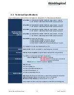
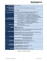
2.3. Technical Specifications
Each
Thinklogical
®
Camera Fiber-Link System is designed to the following specifications:
Electrical Cable
(supplied with
system)
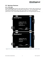
CFL-3000:
(1) CBL000007-002MR MDR-26 male cable, 2 meters
(1) KIT-000013 CAMERALINK W/RJ45 adapter/cable kit
CFL-4000:
(2) CBL000007-002MR MDR-26 male CABLE, 2 meters
(1) KIT-000013 CAMERALINK W/RJ45 adapter/cable kit
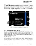
CFL-5000:
(2) CBL000007-002MR MDR-26 male CABLE, 2 meters
(1) KIT-000013 CAMERALINK W/RJ45 adapter/cable kit
CFL-6000:
(2) CBL000007-002MR MDR-26 male CABLE, 2 meters
(1) KIT-000013 CAMERALINK W/RJ45 adapter/cable kit
KIT-000013
contains the following:
(1) ADP-000007 DB9M TO RJ45F Adapter
(1) ADP-000008 DB9F TO RJ45F Adapter
(2) CBL000001-002MR CAT5 cable assembly, 2 meters
For Adapter Pin-outs, see Appendix B, pg. 32.
Serial
RJ45
(DB9M to RJ45 and DB9F to RJ45 adapters included)
Protocol
Camera Link compliant
(supports base/medium/full configurations)
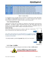
Indicators
Two LEDs on each Camera Fiber-Link module:
Loss of Signal
[LOS] (
Red ON
if no signal)
(
Red BLINKS
if no camera is connected)
(
Red OFF
for good connection)
Power
(
Green ON
when power is applied)
Optical Cable
Fiber Count:
CFL-3000 (Base):
2
CFL-4000 (Full/Medium/Base):
3
CFL-5000 (Dual Base):
3
CFL-6000 (Dual Base RX):
4
Fiber Type:
Multi-mode, 50/125um or 62.5/125um SC-type connectors
Fiber Connector Type:
SC Standard / ST or LC Optional
Maximum Fiber Distance:
See Appendix C, pg. 33
(Fiber Cable is either customer-supplied or ordered from Thinklogical)


