


T9901008-1-1 UK (v9)
Page | 21
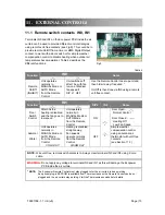
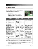
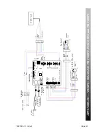
F1 = F100mA
F2 = T6.3A
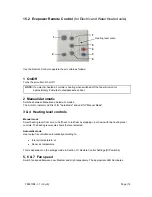
1
2
3
4
ON
REM
O
TE
C
O
NT
RO
L
To
S
la
v
e
A
ir Curtain
M
a
s
te
r/
S
la
v
e
C
a
b
le
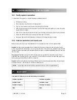
IN
1
IN
0
LED
J2
NC
C
N
O
J1
H
ig
h
s
peed
Me
d
s
p
eed
Low s
p
ee
d
0V
H
ig
h
s
peed
Me
d
s
p
eed
Low s
p
ee
d
0V
Fan 2
Fan 1
J1
7
E
C
O-
Po
w
e
r
CV
R10
0
8
-9
10
9
8
7
6
5
4
3
2
1
L3
N
L2
L1
J1
0
J1
6
J1
2
J5
J6
J1
1
R 0 -10V
J1
4
Th
EEP
R
O
M
F2
F1
J9
Alarm
Healthy
B
lack
re
c
tan
gle
is
mov
e
a
b
le he
ad
of
D
IP
switch
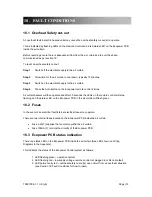
A1
A2
13
N
O
14
N
O
1
2
3
4
5
6
CO
NTA
C
T
O
R
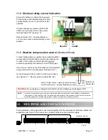
230
V
AC
Co
il
Br
o
w
n
Bla
c
k
Grey
TE
RM
IN
A
L
BL
O
C
K
L1
L2
L3
N
E
L1
L2
L3
N
E
4
00V / 3ph /
50
Hz
Br
o
w
n
Br
o
w
n
Bl
u
e
Bl
u
e
Su
mm
e
r/
Wint
e
r
or
D
oor
Co
nt
act
Bl
u
e
Br
o
w
n
Br
o
w
n
Bla
c
k
Grey
Fi
rs
t St
ag
e He
at
in
g
(b
o
tto
m e
lements)
S
e
c
o
n
d
Stag
e Heatin
g
(to
p
el
ement
s)
3 kW (x3)
Bl
a
c
k
B
la
ck
Bl
a
c
k
B
la
ck
3 kW (x3)
0
1
2
3
4
1
~
Whi
te
(C
O
MMO
N
)
B
la
c
k
(
H
igh)
Bl
u
e
R
ed (
low
)
Y
e
llo
w
Bl
a
c
k
Bl
u
e
Re
d
Wh
it
e
Fan Mot
o
r
1
Whit
e
Bl
a
c
k
Blu
e
Re
d
Ca
pa
ci
to
r:
7.5µF
Re
d
85
°C A
u
to
Thermal Tr
ip
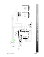
APPENDIX 2B — WIRING DIAGRAM PHV1500E


