ThermoProbe TL2-A Instructions For Use Manual Download Page 5

06/2015, JK 

Polling Mode 

(AC powered unit only)

 
You can set the TL2-A to send data on command. This is useful for people who write data collection software that will request data 
only when it is needed. To place the TL2-A in polling mode, select “PoLL” as the sample rate to be used under the recording section 
of the TL2-A menu. (See Interface Menu Diagram) When the PC sends a question mark character (?) to the TL2-A, the TL2-A will 
respond with the temperature. When the TL2-A is set to flash record mode, the polling feature will not work. 


Temperature controlled Relay 

(AC powered unit only)

:


The TL2-A comes equipped with a switchable relay. This relay will toggle whenever the temperature crosses the set point threshold 
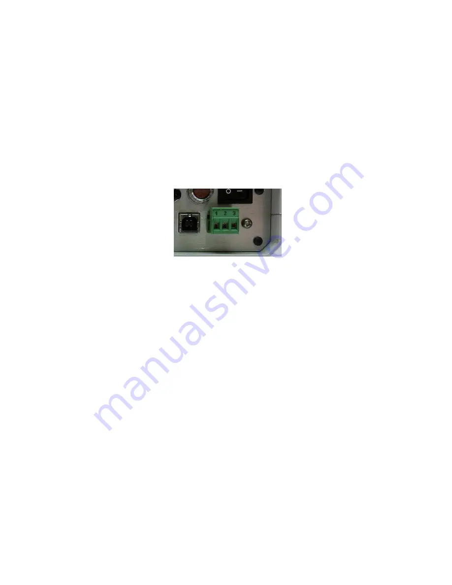
set through the user menu. The provided screw-terminal header can be wired in two configurations: 


Terminals 1-2 are normally closed (NC) and will turn OFF (open) when the relay is set.


Terminals 1-3 are normally open (NO) and will turn ON (close) when the relay is set.


Figure 1: Relay screw-terminal header 


The relay function can be implemented from the user menu. For the relay function to be active, the user must select ‘EnAbLE’ from 
the relay menu. Also from the relay menu, the temperature set point can be configured. (‘rELAY’ -> ‘SEt’) Use the Up & Down 
buttons to select the desired setpoint. Use the select button to select each digit to modify.  Ensure this setpoint is correct before 
selecting the ‘EnAbLE’ function. The relay set point will remain the same regardless of the unit selection (C, F or K). 
 
Once the relay has been toggled, it will remain in that state until the user disables it using the Select button. If desired, the user will 
then need to re-enable the relay from the user menu. 


Summary of Contents for TL2-A

Page 1: ...memory interface User programmable relay output interface Temperature triggered Detachable AC power cord IP50 enclosure rating Adjustable Zero Offset correction Cautions The TL2 A and associated tempe...

Page 2: ...for channel 1 and channel 2 navigates the menu display next previous menu item Also adjusts the zero correction when in the Zero Adjust Mode Channel Indication Marker indicates which channel is curre...

Page 3: ...elsius F Fahrenheit AbS Kelvin o Ohms Hds Hundredths tHoU Thousandths UPdAtE Communication mode for coefficient update FLASH PC rAtE StArt StoP donE Select to Exit Menu 1 sec 10 sec 30 sec 60 sec 1 hr...

Page 4: ...is not detected 4 The up down arrow indicator will blink on the LCD display to indicate that logging is in process 5 To stop the data logging select FL StoP from the menu Wait for the FL DonE message...

Page 5: ...e provided screw terminal header can be wired in two configurations Terminals 1 2 are normally closed NC and will turn OFF open when the relay is set Terminals 1 3 are normally open NO and will turn O...

Page 6: ...isplay will show the zero correction for the selected channel and then return to temperature display mode 5 To save the zero correction the Power Button must be pressed This will set the unit to Stand...

Page 7: ...lick Next 8 On the next screen click Install from a list or specific location Advanced and click Next 9 On the next screen select Search for the best driver in these locations Check the Search removab...

Page 8: ...5 JK 10 The wizard will complete the installation of the software NOTE If your PC should start a new Found New Hardware Wizard it may be necessary to repeat the above steps to complete the driver inst...

Page 9: ...Coefficient Entry The Sensor Data software included with the TL2 A USB flash drive allows the user to input sensor coefficients Install the software by browsing to the SensorData folder on the drive a...

Page 10: ...ction screen A window will open a message stating TL2 A data successfully transferred Select OK to clear this window Once completed the Calibration Data screen will appear 6 Enter the unit serial numb...

Page 11: ...L2 A Note Hyperterminal is no longer included with Windows 7 systems A copy of Hyperterminal is included with the TL2 A software USB flash drive and can be run from that location Click start Accessori...

Page 12: ...12 06 2015 JK Select the Com Port for the TL2 A and click OK NOTE See Finding Com Port Section if you don t know which com port to select Set the Port Settings as shown and click OK...

Page 13: ...w a and wait for a command Toggle Prompt off cr Resume sending temperatures Set Date D YY MM DD cr Set the TL2 A s real time clock s date Set Time T HH MM SS cr Set the TL2 A s real time clock s time...

Page 14: ...Response failure Rate Format R X X 1 10 30 60 3600 Poll cr lf Remarks The brackets contain the options separated by commas e g R 10 cr R poll cr A lower case r or the word Rate or rate can be used En...

Page 15: ...he text as follows Date YY YY MM DD 3 To change the time enter the text as follows Time HH MM SS Saving a file from HyperTerminal 1 From the HyperTerminal menu bar click Transfer Capture Text 2 Enter...

Page 16: ...TL2 A Com Port You can find the Com Port that was installed by clicking on start choosing Settings choosing Control Panel and then opening the System application Click the Hardware tab and then click...

Page 17: ...note the COM number You can use this COM port number to connect to Hyperterminal or other serial communications programs T Th he er rm mo oP Pr ro ob be e I In nc c 112A JETPORT DR PEARL MS 39208 Tel...

Reviews: