ThermoProbe TL2-A Instructions For Use Manual Download Page 4

06/2015, JK 

 
NOTES:


All displayed values and changes are for the current selected channel only


To save settings, the Power Button must be pressed. This will set the unit to ‘Standby’. 


The low, average and high readings are cumulative from the time the TL2-A is powered on. They are 
not saved when the TL2-A is shut down or put in standby and will re-start when the unit is turned on. 
The low, average, and high readings will be displayed once the TL2-A's readings have stabilized (about 
22 seconds.) 


USB Flash Drive Logging 

(AC powered unit only)


1.


Insert a flash drive into the USB1 type ‘A’ socket on the back of the TL2-A. 

2.


From the record menu, select ‘FLASH’ and ‘StArt’. 

3.


The TL2-A display will flash ‘ACCESS’ until the flash drive recording has started. (A ‘no DSC’ message will appear if the 
flash drive is not detected). 

4.


The up/down arrow indicator will blink on the LCD display to indicate that logging is in process. 

5.


To stop the data logging, select ‘FL StoP’ from the menu. Wait for the ‘FL DonE’ message to display before removing the 
flash drive from the TL2-A. (If the drive is removed before the logging has been stopped, the data will be lost.) 


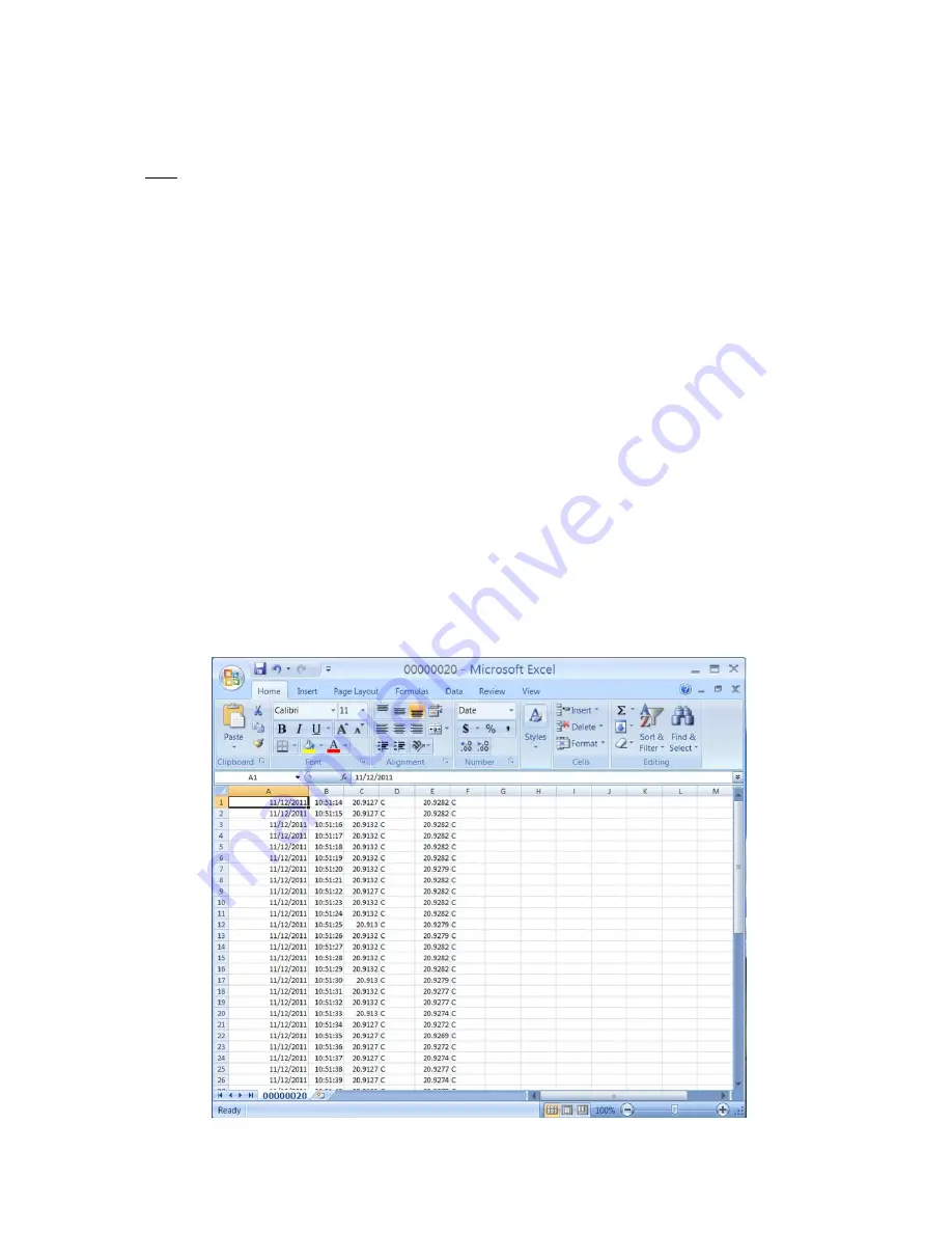
Once the flash drive data logging has been completed, the data can be opened on a standard PC. 

Note: Each time the TL2-A records to the flash drive it will create a new file numbered sequentially higher than the previous file. 
(ex: 0001.csv, 0002.csv, etc.) 
 

1.


Remove the flash drive from the TL2-A. 

2.


Insert the flash drive into a USB port on the PC. 

3.


Browse to the folder containing the flash drive contents. 

4.


The TL2-A data will be contained in a .csv file that can be opened with either Microsoft Excel or a text editor such as 
Notepad. 

5.


The column format is as follows: Date, Time, Channel 1 reading, Channel 1 units, Channel 2 reading and Channel 2 units. 


Summary of Contents for TL2-A

Page 1: ...memory interface User programmable relay output interface Temperature triggered Detachable AC power cord IP50 enclosure rating Adjustable Zero Offset correction Cautions The TL2 A and associated tempe...

Page 2: ...for channel 1 and channel 2 navigates the menu display next previous menu item Also adjusts the zero correction when in the Zero Adjust Mode Channel Indication Marker indicates which channel is curre...

Page 3: ...elsius F Fahrenheit AbS Kelvin o Ohms Hds Hundredths tHoU Thousandths UPdAtE Communication mode for coefficient update FLASH PC rAtE StArt StoP donE Select to Exit Menu 1 sec 10 sec 30 sec 60 sec 1 hr...

Page 4: ...is not detected 4 The up down arrow indicator will blink on the LCD display to indicate that logging is in process 5 To stop the data logging select FL StoP from the menu Wait for the FL DonE message...

Page 5: ...e provided screw terminal header can be wired in two configurations Terminals 1 2 are normally closed NC and will turn OFF open when the relay is set Terminals 1 3 are normally open NO and will turn O...

Page 6: ...isplay will show the zero correction for the selected channel and then return to temperature display mode 5 To save the zero correction the Power Button must be pressed This will set the unit to Stand...

Page 7: ...lick Next 8 On the next screen click Install from a list or specific location Advanced and click Next 9 On the next screen select Search for the best driver in these locations Check the Search removab...

Page 8: ...5 JK 10 The wizard will complete the installation of the software NOTE If your PC should start a new Found New Hardware Wizard it may be necessary to repeat the above steps to complete the driver inst...

Page 9: ...Coefficient Entry The Sensor Data software included with the TL2 A USB flash drive allows the user to input sensor coefficients Install the software by browsing to the SensorData folder on the drive a...

Page 10: ...ction screen A window will open a message stating TL2 A data successfully transferred Select OK to clear this window Once completed the Calibration Data screen will appear 6 Enter the unit serial numb...

Page 11: ...L2 A Note Hyperterminal is no longer included with Windows 7 systems A copy of Hyperterminal is included with the TL2 A software USB flash drive and can be run from that location Click start Accessori...

Page 12: ...12 06 2015 JK Select the Com Port for the TL2 A and click OK NOTE See Finding Com Port Section if you don t know which com port to select Set the Port Settings as shown and click OK...

Page 13: ...w a and wait for a command Toggle Prompt off cr Resume sending temperatures Set Date D YY MM DD cr Set the TL2 A s real time clock s date Set Time T HH MM SS cr Set the TL2 A s real time clock s time...

Page 14: ...Response failure Rate Format R X X 1 10 30 60 3600 Poll cr lf Remarks The brackets contain the options separated by commas e g R 10 cr R poll cr A lower case r or the word Rate or rate can be used En...

Page 15: ...he text as follows Date YY YY MM DD 3 To change the time enter the text as follows Time HH MM SS Saving a file from HyperTerminal 1 From the HyperTerminal menu bar click Transfer Capture Text 2 Enter...

Page 16: ...TL2 A Com Port You can find the Com Port that was installed by clicking on start choosing Settings choosing Control Panel and then opening the System application Click the Hardware tab and then click...

Page 17: ...note the COM number You can use this COM port number to connect to Hyperterminal or other serial communications programs T Th he er rm mo oP Pr ro ob be e I In nc c 112A JETPORT DR PEARL MS 39208 Tel...

Reviews: