


N
E
P
E
L1
L2
Line Side
Chassis Gnd
1
8
GRN/YEL
L1 BLK
L2 WHT
J1
1
8
Power Entry Module
Fuses: [2] 3.15 Amp
Controller
Board
+
Solid State
Relay
5 BLK
2 RED
1 RED
6 WHT
5 BLK
6 WHT
L1 WHT
L2 WHT
AC Input
HTR
MTR
Wire Harness
Plug
Heater Unit
High Limit
Thermostat
GRN/YEL
Wire Harness
Plug
7 BLK
8 WHT
7 BLK
8 WHT
AC
GRN/YEL
7 BLK
8 WHT
7 BLU
GRN
3 GRY
4 GRY
Seal Switch
LS1
LS2
Motor Control
Switch
8 BLU
Wire Harness
Plug
5 YEL
6 YEL
RED
YEL
PT1600
RTD
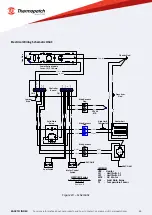
HS3C/4C Series
Electrical Schematic
230 Volt
Revision B
CN2
CN1
SSR
MTR
HTR
Press Arm
Gnd
LEGEND:
HTR - Heater
LS1 - Limit Switch 1
LS2 - Limit Switch 2
MTR - AC Motor
SSR - Solid State Relay
TS - Temperature Sensor
LS2
TS
LS1
SSR
R1
L1
5
R2
Capacitor
Jumper
Wire
HS4C ONLY
HS4C ONLY
20
For more information about our products and how to contact us, please visit thermopatch.com
Figure 13 – Schematic
Electrical Wiring Schematic HS4C


