FLX
TM
Self-Regulating
4
Table 1: Valve and Pump Allowances
Heating Cable
12” Max.
(30 cm)
Note:
Flange allowance will vary based on method of insulating flange and adjacent piping.
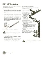
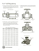
4. Flanges: Allow cable to be looped around pipe on each side
of and adjacent to the flange. Heating cable must maintain
contact with flange when bending around pipe flanges to
compensate for additional heat loss.
Attachment Tape
(Typical)
Heating Cable
Temporary Loop of Cable on Valve
Attachment Tape
(Typical)
Heating Cable Serpentined on Pump
Heating Cable
Attachment Tape
(Typical)
Heating Cable Serpentined on Valve
Typical Pump Detail
Heating Cable
Attachment Tape
(Typical)
Pipe
Size
Valve Type
Screwed Flanged Welded
Pump Type
Screwed Flanged
½"
6"
1'
0
1'
2'
¾"
9"
1'-6"
0
1'-6"
3'
1"
1'
2'
1'
2'
4'
1¼"
1'-6"
2'
1'
3'
4'-6"
1½"
1'-6"
2'-6"
1'-6"
3'
5'
2"
2'
2'-6"
2'
4'
5'-6"
3"
2'-6"
3'-6"
2'-6"
5'
7'
4"
4'
5'
3'
8'
10'
6"
7'
8'
3'-6"
14'
16'
8"
9'-6"
11'
4'
19'
22'
10"
12'-6"
14'
4'
25'
28'
12"
15'
16'-6"
5'
30'
33'
14"
18'
19'-6"
5'-6"
36'
39'
16"
21'-6"
23'
6'
43'
46'
18"
25'-6"
27'
6'-6"
51'
54'
20"
28'-6"
30'
7'
57'
60'
24"
34'
36'
8'
68'
72'
30"
40'
42'
10'
80'
84'
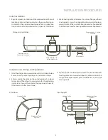
6. Install heating cable on valves and pumps utilizing a looping
technique (this allows the valve or pump to be removed if
required).
5. Additional cable is required to provide extra heat at valves,
pumps and miscellaneous equipment to offset the in-
creased heat loss associated with these items. Refer to
Table 1 for estimated cable requirements for installation on
typical valves and pumps.
Typical Valve Details
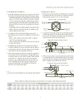
Typical Flange Detail

