2-8
T
HE
A
URORA
-2 H
EAD
CAUTION
To avoid damage to the probe and sample, handle the head with care, pay-
ing particular attention to the probe and probe mount on the bottom. Whenever the head
is removed from the microscope stage, use the Tip Up button
on the Data Acquisition
tool bar to raise the tip a safe distance away from the sample. When placing the head on
the stage, or when carefully setting it down on a table or other flat surface, turn the Z-height
thumbscrews one full turn clockwise. Whenever the head is lowered using the Z motor or
thumbscrews, watch the image on the video monitor to make sure the probe does not crash
into the sample or stage.
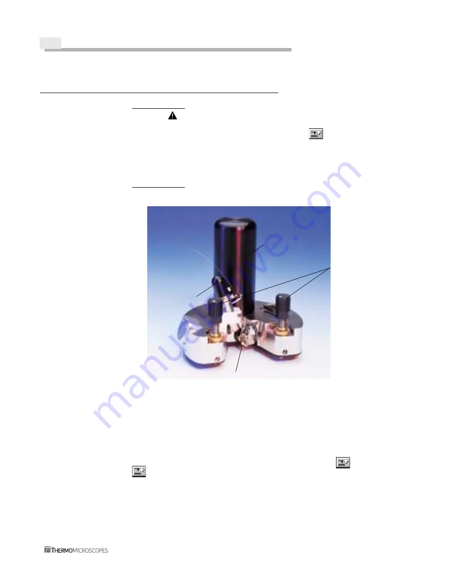
Figure 2-7
Aurora-2 Head
The Aurora-2 head rests on a kinematic mount on the instrument base, as shown in
Figure 2-8 (note that there is also a kinematic mount for the Explorer head). The Z-height
between the probe and the sample stage is controlled by the three Z-height screws, as shown
in Figure 2-9. On the bottom of each screw is a ball bearing that fits into the kinematic
mount. The motorized screw (Z motor) is controlled with the Tip Up
and Tip Down
buttons on the Data Acquisition tool bar in the SPMLab software. The other two
screws are adjusted manually with the thumbscrews on the head.
Z-height
Light
Probe
Z motor
thumb screws
Summary of Contents for Aurora-2
Page 30: ...2 18 Figure 2 20 Reflection Tower Controls Swivel Tilt Focus Rotating mirror selector ...
Page 44: ...3 8 ...
Page 52: ...5 4 ...
Page 54: ......


