background image

29

KEYPAD LOCK

The keypad may be locked or unlocked when this window is selected.

To lock, press the 

 key and hold for 5 seconds.

To unlock, press the 

 key and hold for 5 seconds.

When the keypad is locked, the SM DUE enters into a security mode, which renders
the unit ‘tamper-proof’.

There are three functions for which the set keys (

 / 

) will operate when the

keypad is locked.

(a)

Display contrast (see 3.2.1 MAIN SCREEN 1);

(b)

Alarm mute and reset (see 3.3.2 System Pre-sets);

(c)

Entering the Diagnostics Screen for viewing (see section 3.4).

CE

This product has been tested to the EU EMC 89/336/EEC directive according to the
Manufacturer’s report, which is available on request.

This product is in conformance with the Low Voltage Directive 73/23/EEC.

Thermomax certifies that this datalogging and / or control device has been
manufactured to an ISO 9002 Quality System.

Thermomax undertakes to repair or replace the device if same is shown to be
defective in its manufacture and / or components, but Thermomax shall not be
responsible for any other financial or economic loss (or any indirect loss) which may
be incurred by the buyer / customer or others in the use of the device.

Any claim for repair or replacement must be made not later than 15 months after the
date of manufacture.

Summary of Contents for SM DUE

Page 1: ...THERMOMAX SM DUE TWO CHANNEL DATALOGGER AND ALARM ENGLISH www Thermomax Group com ...

Page 2: ...T SCREEN 3 System Pre sets 2 13 3 4 SYSTEM DIAGNOSTICS 3 4 1 DATABANK DIAGNOSTICS SCREEN 14 3 4 2 CHANNEL DIAGNOSTICS SCREEN 15 3 4 3 CALIBRATION TRIMMING SCREEN 16 3 5 CHANNEL SCREENS 3 5 1 CHANNEL DISPLAY SCREENS 17 3 5 2 CHANNEL SET SCREENS 18 3 6 PLOT HISTORY 3 6 1 Data log of previous days 19 3 7 DATA TRANSFER 20 3 7 1 Transferring Data Using the Masterlink Software 20 3 7 2 Transferring Data...

Page 3: ... databank used indication in bargraph and digital form Once the databank is 100 full the first eighth of the stored data will automatically be replaced For the capacity of the databank see Section 5 Power Supply options of either Mains or DC Contents of internal databank can be transferred directly to the PC using the MASTERLINK Software or via a MASTERLINK Hardware module to a PC at a remote site...

Page 4: ... to the mains supply and the cover is opened circuits at mains voltage will be exposed Therefore when installing the unit ensure all required connections including battery connection if included are made and covers replaced before turning on the mains supply Ensure that all the connections made are secure If any maintenance work is required e g installing a new battery ensure that the unit is isol...

Page 5: ...r entry mark the entry holes in the panel behind the appropriate knock out entries as well as the two lower mounting holes Remove the moulding drill the necessary holes in the panel assemble any grommets or conduit adapters if used replace the moulding and fasten using the two lower screws 2 2 SENSORS Temperature sensors SXTM PT100 are used with all Thermomax units They are available in lengths fr...

Page 6: ...lication Alarm Relay L E N Connect as appropriate to application Mains Input 220 240V AC DC Input 20 28V DC Sensors CH1 CH2 SWITCH OPEN DOOR OPEN SWITCH CLOSED DOOR CLOSED Door max 5A PC 2 5 BATTERY The battery supplied is a 9V PP3 nickel metal hydride rechargeable battery and is attached to the lid of the terminal compartment but not plugged in This should be plugged in after installation This ba...

Page 7: ...Screen 1 2 FUNCTIONKEYS There are six function keys on the SM DUE datalogger Main Screen 1 Channel 2 Display Screen Main Screen 2 Channel 2 Set Screen Set Screen 1 Plot History Screen Set Screen 2 Channel 1 Display Data Transfer Key Screen Channel 1 Set Screen 3 SELECTKEYS Within each function there are some parameters that can be selected for setting or displaying purposes The keys allow the requ...

Page 8: ...at facility press and hold the key in order to advance quickly Note The and keys are the only keys which can alter the value of a selected parameter Other keys may be pressed to view or select these parameters without effecting any change in the system 5 INDICATORS The System Alarm can be triggered by the high temperature alarm low temperature alarm or by a sensor fault 7 DATA TRANSFER IN PROGRESS...

Page 9: ...mperature display viewed in either C or F 3 High and Low Alarm Limits for each channel plus date of last alarm 4 Maximum and minimum daily temperatures for each channel Note The display contrast may be adjusted in this screen Press to increase and to decrease the contrast To adjust quickly press and hold for auto repeat 2 3 5 1 4 ...

Page 10: ...o move the time bar to the left The status of the current time bar is detailed at the bottom of the screenas per 4 6 below 4 Plot Time This displays in digital form the time indicated by the time bar The time is displayed in 5 minute sample intervals 5 Plot Date This shows the date of the currently displayed graph 6 Time Bar Temperature This displays the logged temperature at the time indicated by...

Page 11: ... The indicates that the day on the calendar above is being set The clock is in 24 hour format To advance quickly press and hold the or key for auto repeat 3 Calendar This is the calendar of the month selected with day of the week indication SETTING THE DATE AND TIME Step 1 Use the keys to set the current Year Step 2 Use the key to move to the Month option and then use the keys to set the current m...

Page 12: ...ping within pre set limits the alarm mute will be cancelled automatically 3 Alarm Reset Any current activities delays or counters are reset by pressing the key when the RESET window is selected 4 Alarm Relay Status The output status of the alarm relay may be either viewed or altered by pressing the or key when the RELAY window is selected 0 Relay Manually disabled ALARM ON AUTO For normal operatio...

Page 13: ...tion 3 2 2 This option may be enabled or disabled by pressing the or key respectively The diagram in section 2 4 shows how to connect a door switch 8 Temperature Scale The scale used by the system to communicate the temperature information may be selected here Press for C and for F 9 Diagnostics By pressing the key when the DIAG window is selected the SM DUE DIAGNOSTICS screen is activated see nex...

Page 14: ...seconds respectively When the sensor input is switched ON the unit will operate in normal mode and the actual sensor temperature will be monitored and logged to the databank every 5 minutes If the sensor input is switched OFF the unit will display 0 C continuously This value will also be logged to the databank Hence it is therefore only necessary to connect sensors to the required number of inputs...

Page 15: ...TL window shows the total number of alarm incidences which have occurred in the current year 5 The LAST ALRM window shows the last date on which an alarm condition occurred 6 The TRANSF ON window shows the date on which the contents of the internal databank need to be transferred 7 The POWER FL window shows the last date on which the power failed During a power fail situation this window will disp...

Page 16: ... The CALIB DATA window shows calibration values for factory use only and the current temperature reading 4 The LAST CALIB window shows the date when the SM DUE was calibrated in this case 5 JAN 99 5 The AL HIGH window shows the date when the last high alarm condition occurred for this channel 6 The AL LOW window shows the date when the last low alarm condition occurred for this channel 1 2 3 4 5 6...

Page 17: ... A known reference temperature should be used SM DUE CALIBRATION PLEASE REFER TO MANUAL To enter the CALIBRATION TRIMMING Screen press and hold the key for 5 seconds SM DUE 11 10 CHAN 1 0 0 CHAN 2 Use the keys to move to the channel that requires calibration trimming Then use the or keys to adjust the current temperature reading ...

Page 18: ...and minimum high and low temperature alarms respectively 5 Digital display of Channel temperature with minimum maximum indication The minimum and maximum values are daily values and are reset at midnight 6 Internal databank indicator This indicates the percentage used in both bargraph and digital form 7 When the door switch facility is activated see 3 3 2 this area will show the status of the door...

Page 19: ...ure related alarm If the maximum threshold is exceeded a timer is initiated and no further action is taken at this time 5 High Alarm Stage 1 Delay 1 99 min After the maximum threshold has been exceeded Ref 4 above the alarm will not be triggered until the timer exceeds the time delay set here If the temperature drops below the threshold before the expiry of this delay the timer is reset If followi...

Page 20: ...he plot of a particular day select the required month from the calendar using the keys followed by the key to accept the selection A second screen appears for the selection of the day after which the logged data for the required day is displayed for inspection Ref Section 3 2 2 MAIN SCREEN 2 Current Day Plot Screen When the required plot is displayed the plot screen for either of the channels may ...

Page 21: ...er the MASTERLINK Software Manual a Plug the 8 Way SX plug of the PC Cable Assembly into the SERIAL LINK of the SM DUE b Then plug the 9 Way female D type connector into any free serial port in the PC NOTE For Panelmount units read section 3 8 before attempting to download or print data 3 7 2 Transferring Data to the Masterlink Hardware a Connect the MASTERLINK Cable Assembly from the SERIAL LINK ...

Page 22: ...day up to the total number of days stored in the internal databank of the Thermomax unit In this example there are 61 days of data stored in the Databank e To increase or decrease the number of days to download press the or key and then press the key to confirm this The maximum number of days the user will be able to download corresponds to the number of days data stored in the databank ...

Page 23: ...ar SM DUE PRINT 0002 DAYS MAX 91 DAYS INCREASE DECREASE CONFIRM c The user can now choose any number of days starting from the current day to print directly to the Thermomax serial Printer from 1 day up to the total number of days stored in the internal databank of the Thermomax unit In this example there are 61 days of data stored in the Databank d To increase or decrease the number of days to pr...

Page 24: ...momax Serial Printer A6747 Masterlink Hardware Unit C0321 PC Mode 2 This mode is used to network up to 32 units to one PC see illustration below SM QUATTRO PANELMOUNT C0445 SM DUE PANELMOUNT C0447 NETWORK CABLE 1m A7004 10m A7426 20m A7427 50m A7428 100m A7429 200m A7431 NETWORK TERMINATOR A7256 NETWORK TERMINATOR A7256 MASTERLINK SOFTWARE C0322 5m CABLE ASSEMBLY DISK MASTERLINK EXTENSION KIT 10m ...

Page 25: ...llowing screen will appear SM DUE DATA TRANSFER FUNCTION NOT AVAILABLE PLEASE REFER TO MANUAL In order to download data to the Masterlink Hardware unit or print directly to a Thermomax Serial Printer the network must be disabled To disable network press the key twice to reveal the following screen SM DUE Select the window by using the key and press the key to show the following screen 24 ...

Page 26: ...hold the key for approximately 10 seconds The following screen will appear SM DUE To disable the network press the key When the key is pressed the SM Due will switch off and back on again If you do not wish to disable the network press the key 25 ...

Page 27: ...mode press the key twice to reveal the following screen SM DUE Select the window by using the key and press the key to show the following screen SM DUE With this screen displayed press and hold the key for approximately 10 seconds The following screen will appear 26 ...

Page 28: ...close to a mains cable Tighten connections and re route cables if necessary Problem Unable to set any of the parameters Keypad will not operate Cause Remedy The Keypad Lock is on See Keypad Lock Problem The display screen is too dark or too faint Cause Remedy Adjust the display contrast to suit See Display Contrast in the MAIN SCREEN 1 section Problem The System Alarm light is flashing once every ...

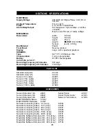
Page 29: ...28 days PARTS LIST SM DUE Unit 24V C0403 SM DUE Unit 12V C0419 Sensor 5m cable A6905 Sensor 15m cable A6915 Sensor 25m cable A6925 Sensor 50m cable A6950 Sensor 100m cable A7999 ACCESSORIES Sensor Extender 10m A6911 Serial Printer A6747 Sensor Extender 20m A6921 Serial Printer Cable A7433 Sensor Extender 50m A6951 Network Terminators A7256 MASTERLINK Software C0322 MASTERLINK Hardware C0321 Networ...

Page 30: ...s product has been tested to the EU EMC 89 336 EEC directive according to the Manufacturer s report which is available on request This product is in conformance with the Low Voltage Directive 73 23 EEC Thermomax certifies that this datalogging and or control device has been manufactured to an ISO 9002 Quality System Thermomax undertakes to repair or replace the device if same is shown to be defect...

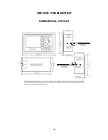
Page 31: ...30 SM DUE PANELMOUNT DIMENSIONAL DETAILS ...

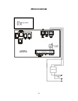
Page 32: ...31 WIRING DIAGRAM Alarm Relay max 5A 220 240 VAC 50Hz Transformer 12V THERMOMAX PANEL MOUNT NOTE For SM DUE applications CH1 CH1 CH2 CH2 L N E ...

Reviews: