Thermo DCT7088 User Manual Download Page 27

22

..... Additional setup menus within the OPTIONS submenu

6.

Unit ID (identification) Number

 setup menu (49): This number is determined by the operator to identify

the specific instrument or site. Any whole number between 1 and 60,000 may be entered
(Figure 3.12-N, below).

F

IGURE

 3.12-N

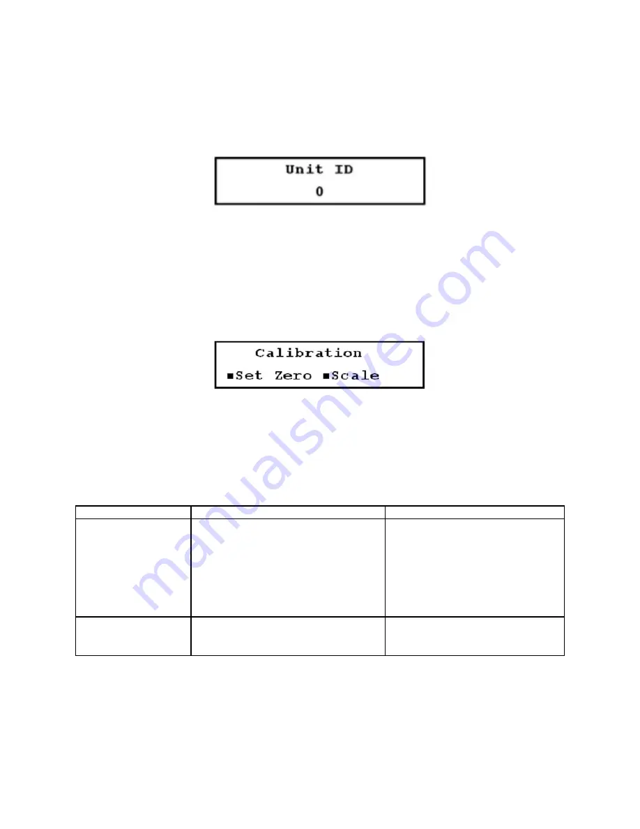
3.13 Additional Setup Menus Within the CALIBR Submenu

*Not included in the Quick Setup configuration

Within the 

CALIBR

 submenu is the 

Calibration Group 

menu (50) (Figure 3.13-A, below), which contains 4

setup menus: 

Zero Set, Scale, SS Comp, Date 

(Menus 51 through 54).

F

IGURE

 3.13-A

3.13.1 Zero Set Calibration

An important step in assuring accurate flow measurement is the proper calibration of the instrument and
proper installation. The calibration methods must be performed for the particular pipe that is to be metered.
Table 3 (below) provides guidelines for selecting a calibration method.

Calibration Method

Function

Application

Zero set calibration

Zero flow set

Zeroes the instrument for an actual no

Installations where flow can be

flow condition

stopped

Manual zero set

Applies a manually entered offset to

Where an offset is required

all flow readings

Scale factor

Compensates for manufacturing

Set by the factory to the value

variations in the transducers

imprinted on the transducers

T

ABLE

 3

After installing the meter, you may find that a small adjustment to the zero point (zero set calibration) is
required. Zero set calibration allows the meter to read very close to zero under zero flow conditions. There
are two zero set calibration methods in Menu 51: the zero flow set method and the manual zero set
method. View the zero point used by the flowmeter in either of these methods by selecting 

Manual

 in Menu

51.

Summary of Contents for DCT7088

Page 1: ...DCT7088 PORTABLE DIGITAL CORRELATION TRANSIT TIME ULTRASONIC FLOWMETER P N 1 0561 007 Rev C 04 04 USER MANUAL ...

Page 2: ...r personal and system safety and for optimum performance make sure you thoroughly understand the contents before installing using or maintaining this instrument For equipment service needs outside the United States contact your nearest Thermo Electron representative Within the United States Thermo s service department is your single point contact for all Thermo equipment service needs If at any ti...

Page 3: ...he material in this manual is proprietary and cannot be reproduced in any form without express written consent from Thermo Trademarks Copyrights Acknowledgements for trademarks copyrights used in this manual belong to Dow Corning is a registered trademark of Dow Corning Corporation Excel for Windows is a registered trademark of Microsoft Corporation IBM is a registered trademark of International B...

Page 4: ... 5 Signal Strength Low Signal Cutoff 04 14 3 7 Additional Setup Menus Within the PIPE Submenu 15 3 8 Additional Setup Menus Within the LINER Submenu 15 3 9 Additional Setup Menus Within the FLUID Submenu 16 3 10 Additional Setup Menus Within the FLOW Submenu 16 3 11Additional Setup Menus Within the TOTAL Submenu 18 3 12Additional Setup Menus Within the OPTIONS Submenu 19 3 13 Additional Setup Menu...

Page 5: ...arging the Printer Battery 46 6 3 Charging the Flowmeter 47 6 4 Replacing Sonic Coupling Compound 47 6 5 Troubleshooting Support 48 6 5 1 General 48 6 5 2 Local Representative Support 48 6 5 3 Service Returns 48 6 5 4 Upgrades 49 6 6 Warranty Statement 49 Appendix A Pipe Schedules 50 Appendix B Fluid Properties 54 B 1 Fluid Sound Velocities Kinematic Viscosities 54 B 2 Clean Water Sound Speed Vers...

Page 6: ... sound in the fluid and the velocity of the fluid itself relative to the transducer A sound wave traveling in the same direction as the fluid flow down stream will arrive sooner than a sound wave traveling against the flow upstream A transit time flowmeter operates by measuring both the absolute travel time of each sound wave and the difference in time required for the waves to travel between an e...

Page 7: ...ile corrections to compensate for the pipe s cross sectional velocity profile with a changing Reynolds number However this requires that the operator knows the inside roughness of the pipe to be measured The instrument may infer a roughness if none is entered by the operator but that is only an estimate based on the characteristics of new pipe Pipes can of course accumulate deposits which may not ...

Page 8: ...s of 10 ft 3 m up to 1000 ft 305 m Additional Options 0704 0188 Ultrasonic Thickness Gauge UTG English units 0704 0187 UTG metric units 22334 0001 Thermal printer kit Typical Model Number DCT7088 1 B 16A 1 standard TABLE 1 ORDERING INFORMATION 1 5 Technical Specifications 1 5 1 Performance Flow Range 0 to 40 ft s 0 to 12 m s Accuracy 0 5 of velocity or 0 05 ft s 0 0152 m s typical digital output S...

Page 9: ... points time stamped programmable in 1 second intervals Programming Via UltraScan utility supplied with flowmeter OR integral keypad Temperature Range Transducers 40º to 212º F 40º to 100º C Optional High temperature transducers available Transmitter 5º to 140º F 20º to 60º C 1 5 3 Physical Transmitter NEMA 6 IP67 waterproof against accidental immersion splashproof with lid open Transducers Encaps...

Page 10: ...pending on battery type Automatic shutdown after approximately 1 additional hour 4 Charging light 5 Instrument on light 6 Fuse 3 A 250 V Protects flowmeter from battery overcurrent or short circuits 7 Liquid crystal display LCD Displays configuration selections flow rate totalized flow etc 8 Keypad Use to enter configuration parameters and control flowmeter functions 9 Downstream transducer connec...

Page 11: ...ter 4 4 20 mA output terminals 5 Printer charger cable 6 RS232 serial port 7 Breakout box interface connector Provides connections for DC power input from battery charger AC adapter for DC output cable for charging battery for RS232 serial port and for 4 20 mA current loop output terminals 8 7 pin circular connector Connects breakout box to flowmeter FIGURE 1 7 ...

Page 12: ...ust be driven from an external power supply In this case the flowmeter acts as a passive 2 wire transmitter Prevent possible electrical shock and or damage to the meter disconnect power PRIOR to removing back cover of the breakout box and disconnect the breakout box from the flowmeter and battery charger AC adapter To connect the current loop 1 Ensure the loop powering option is correct 2 Locate t...

Page 13: ...PLAY FEATURES 3 1 2 Display Contrast Backlight The display is backlit for ease of viewing in low light conditions In order to save battery life the backlight shuts off automatically after several minutes have passed without a keypad entry The display has a variable contrast setting and you may need to adjust the contrast on the display as ambient temperature changes 1 Press MENU followed by the pl...

Page 14: ...ime 54 Liner Liner Material 16 Liner Thickness 17 Current Loop 56 Liner Sound Speed 18 Current Loop Span 57 Liner Inside Roughness 19 Current Loop Calibration 58 Current Loop Test 59 Fluid Fluid Type 20 Fluid Sound Speed 21 Alarms 70 Fluid Viscosity 22 Program Alarms 71 View Alarms 72 Transducer Transducer Type 23 Transducer Mounting 24 Datalog Datalog Setup 80 Transducer Spacing 25 Datalog Interv...

Page 15: ...Liner submenu options as shown in Figure 3 3 A 2 To view the remaining submenus Figure 3 3 B press the DOWN ARROW key 3 When the desired submenu is highlighted press ENTER to display the first menu of the selected submenu Figure 3 3 C is an example of when the Flow submenu is selected Use the UP or DOWN ARROW keys to view a primary display setup menu or diagnostic menu within the current submenu 3...

Page 16: ...e steps enable the flowmeter to calculate transducer spacing acquire ultrasonic signal and measure flow The number in parentheses after the required menu is the 2 digit address to directly access that menu 1 Select a proper transducer site according to Section 4 page 33 2 Access the Pipe submenu This submenu contains setup menus related to the pipe parameters such as pipe inside diameter ID and pi...

Page 17: ...er a Access the Liner Material setup menu 16 and Figure 3 5 E below is displayed Press the UP and DOWN ARROWS to scroll through the available options Select OTHER if the material is not listed You must then enter the liner sound speed 18 and liner inside roughness 19 b Access the Liner Thickness setup menu 17 and enter the thickness Figure 3 5 F below 4 Access the Fluid Type setup menu 20 and scro...

Page 18: ...s are displayed first followed by the associated time per units a Select one of the available volumetric units Figure 3 5 K below b Press the DOWN ARROW and the time per unit options are displayed Select the desired option Figure 3 5 L below FIGURES 3 5 H THROUGH 3 5 L LEFT TO RIGHT TOP TO BOTTOM 8 Install the transducers on the pipe using the spacing provided by the flowmeter and connect the tran...

Page 19: ...ity is displayed in feet per second FPS if ENGLISH is selected as the measurement unit in Menu 42 and in meters per second MPS if METRIC is selected 3 6 3 Flow Positive Totalizer 02 This display indicates the flow rate and the totalized flow in the positive flow direction If the positive totalizer is not currently enabled the last net totalized value is displayed Figure 3 6 C below 3 6 4 Flow Nega...

Page 20: ...s of the pipe If you did not select OTHER as the pipe material this menu is available by the direct access method only and functions as a view only display to indicate the pipe inside roughness as programmed in the flowmeter s database Figure 3 7 C below FIGURES 3 7 A THROUGH 3 7 C LEFT TO RIGHT TOP TO BOTTOM 3 8 Additional Setup Menus Within the LINER Submenu Not included in the Quick Setup confi...

Page 21: ...thin the FLOW Submenu Not included in the Quick Setup configuration 1 Max Flow Range setup menu 31 and Min Flow Range setup menus 32 Use these menus to enter the minimum and maximum flow values for setting the volumetric flow range Setting the optimum flow range generally improves the flowmeter s response time Figures 3 10 A and 3 10 B page 17 Whenever the pipe ID is changed the flowmeter returns ...

Page 22: ...s less than 0 1 ft s in the positive direction and greater than 0 1 ft s in the negative direction Figure 3 10 E below FIGURES 3 10 D LEFT 3 10 E RIGHT 4 Low Signal Cutoff setup menu 35 Empty pipes or solids bubbles or voids in the flow stream may cause temporary drops in signal strength and erroneous readings Minimize the effect of these dropouts by setting a low signal cutoff which drives the fl...

Page 23: ...sitive and negative flow values For example if there are 1000 gallons of flow in the negative direction and 3000 gallons of flow in the positive direction the net totalizer indicates 2000 gallons of net flow Figure 3 11 C below 4 Positive Totalizer setup menu 39 Use this menu to enable or disable the positive totalizer The positive totalizer tracks the flow that moves in the positive direction fro...

Page 24: ...ite Several sites are available and are numbered The site number isdisplayed in Menu 43 in the lower left corner of the screen and is followed by a colon See Figure 3 12 B below for an example of a site numbered 1 As you enter the setup parameters in their respective menus during normal configuration the same parameters are saved simultaneously in the Site Parameters setup menu in whichever site h...

Page 25: ...ed If a password is enabled the flowmeter requests the password when a user attempts to enter any configuration data Entering the correct password temporarily unlocks the system allowing the user to make configuration changes To change or disable the system password a Access Menu 47 Figure 3 12 E page 21 b Enter the new system password and press ENTER Figure 3 12 F page 21 Disable the system passw...

Page 26: ...abled the flowmeter requests the password whenever a user attempts to change the scale factor To change or disable the scale factor password a Access Menu 48 Figure 3 12 J below b Enter the new scale factor password and press ENTER Figure 3 12 K below The system password function must be disabled to allow the scale factor to be changed without entering a password c Enter the old scale factor passw...

Page 27: ...r the particular pipe that is to be metered Table 3 below provides guidelines for selecting a calibration method Calibration Method Function Application Zero set calibration Zero flow set Zeroes the instrument for an actual no Installations where flow can be flow condition stopped Manual zero set Applies a manually entered offset to Where an offset is required all flow readings Scale factor Compen...

Page 28: ...low rate displayed in Menu 01 must be between 0 25 and 0 25 ft s 0 076 and 0 076 m s 1 Ensure there is no flow in the pipe 2 Access Menu 51 Figure 3 13 B below 3 Select No Flow If the zero flow set calibration is successful Figure 3 13 C below is displayed FIGURES 3 13 B LEFT 3 13 C RIGHT B Manual Zero Set Use this method infrequently Manual zero set applies a constant offset entered by the user t...

Page 29: ...Use only the factory preset scale factor as marked on the transducers in the following situations the flow cannot be stopped to verify or set the zero point a reasonably high flow rate cannot be achieved an accurate secondary flow standard is not available If an additional scale factor is required the additional scale factor should be multiplied by the factory scale factor and the result should be...

Page 30: ... scroll to the next screen with the DOWN ARROW instead of pressing ENTER e Once all parameters are entered the new programmed date and time is displayed FIGURES 3 13 H THROUGH 3 13 J LEFT TO RIGHT TOP TO BOTTOM 3 14 Additional Setup Menus Within the 4 20 mA Submenu Not included in the Quick Setup configuration Within the 4 20mA submenu is the Current Loop Group menu 56 Figure 3 14 A page 26 which ...

Page 31: ...dicated on the screen should be the same as the output on the milliammeter If the values do not match repeat steps 2 through 10 11 Set the current loop span by accessing Menu 57 Figure 3 14 E below The current loop span is the span of flow versus current 12 Enter a flow rate which equals the 4 mA minimum anticipated reading and press ENTER 13 Press the DOWN ARROW and Figure 3 14 F below is display...

Page 32: ...AL alarm activates when signal strength value is greater than ON condition value SIGNAL alarm activates when signal strength value is less than ON condition value 3 Press the DOWN ARROW and Figure 3 15 D page 28 is displayed 4 Enter the value for the alarm ON condition and press ENTER Flow units used for alarms are the same as flow units selected for measuring flow in Menu 30 5 Press the DOWN ARRO...

Page 33: ... RIGHT 3 16 Additional Setup Menus Within the DATA LOG Submenu Not included in the Quick Setup configuration The DATA LOG submenu contains the Log Menu 80 and the Log Interval menu 81 The data logger allows flow data to be continuously recorded at a preset interval The flowmeter has a single data log file with approximately 40 000 data points available When all points are recorded the data logger ...

Page 34: ...t Stop 2 Figure 3 16 B below is displayed press 5 b Auto This option allows you to program the logger for a future start and stop time To use this function 1 Access Menu 80 and select Auto 2 The current programmed start stop times are displayed Figure 3 16 C below 3 Press ENTER Prompts are displayed requesting day hour minute and second information for the start stop times Figure 3 16 D below Pres...

Page 35: ...etup Menus Within the DIAGNOSTICS Submenu Not included in the Quick Setup configuration The DIAGNOSTICS submenu contains various view only menus which display important diagnostic parameters that are currently used or calculated by the flowmeter These parameters are helpful when configuring or troubleshooting the flowmeter 1 Signal Strength Margin display 90 Displays the signal strength in percent...

Page 36: ...guration Following are instructions on how to configure the optional external thermal printer To begin ensure the printer cable is connected to the printer port on the upper left of the flowmeter s control panel 1 Print Log Setup menu 96 Use this menu to configure the printer to print out flow data at a preset interval and or whenever an alarm activates Printed flow data include data from all enab...

Page 37: ... be printed If the print interval is interrupted by a power loss the printer resumes at the specified interval after power is restored 2 Print Settings menu 97 Print all parameters associated with the pipe liner fluid transducer and flow menus 10 35 3 Print Diagnostics menu 98 Print all parameters associated with the DIAGNOSTICS submenu 90 94 4 Print Current Screen menu 99 Print the current displa...

Page 38: ...s FIGURE 4 1 Locate the symbol seen in Figure 4 1 This symbol is on both pairs of terminals and indicate which terminals should connect to the center wire conductors and which should connect to the coaxial shields 4 2 Site Selection Preparation Prior to installing the transducers a proper site must be selected to ensure accurate measurement Examples of site recommendations are illustrated in Figur...

Page 39: ...om the flowmeter after a pump control valve or double piping bend for greater accuracy A distance of 5 diameters downstream is usually sufficient under all circumstances d Always mount the transducers on the sides of the pipe in the 3 o clock or 9 o clock positions on horizontal pipes Positioning the transducers in this manner prevents signal loss which can be caused by sediment along the bottom o...

Page 40: ...nfigure with UltraScan and note the value required for the transducer spacing value calculated by and displayed on flowmeter LCD or in UltraScan 3 Clean the area of the pipe designated as the mounting location Remove any rust scale or loose paint well bonded paint does not need to be removed On horizontal pipes the transducers should be mounted in the 3 o clock and 9 o clock positions in order to ...

Page 41: ...ce is aligned normal to the pipe Figure 4 3 A below The transducer face alignment is particularly critical on small pipes due to pipe curvature Notice that the properly installed transducer contacts the pipe at the pipe s centerline and that the gaps on either side of the centerline are equal The notches on both ends of the portable transducer rack allow the assembly to self align to the curvature...

Page 42: ...IGURE 4 3 C PORTABLE TRANSDUCER RACK INSTALLATION 4 4 Transducer Mounting Methods There are several methods of mounting the transducers The best method is determined by the specific application Complete steps 1 5 in Section 4 3 page 35 and refer to the following sections for instructions on how to properly mount the transducers with one of the available mounting methods 4 4 1 V Method The V method...

Page 43: ... 4 inches 100 millimeters or less can be improved by using the W mounting method Figure 4 4 B below With the W method the sound wave traverses the fluid 4 times and bounces off the pipe walls 3 times Like the V method both transducers are mounted on the same side of the pipe Ensure W is the selected mounting method FIGURE 4 4 B W MOUNT ...

Page 44: ...n the pipe Figure 4 4 D page 40 2 Place a transducer at the 3 o clock position 3 Trace the shape of the 3 o clock transducer along its inside edge opposite the cable connection Draw a horizontal line at its center Remove the transducer Figure 4 4 E page 40 4 Obtain a continuous sheet of paper longer than the circumference of the pipe Calculator paper tape or thermal printer paper works well for th...

Page 45: ...at the line is level with the top of the pipe The line should be at least 3 inches 76 millimeters longer than the transducer spacing calculated by UltraScan For example if UltraScan calculates the spacing as 14 inches 356 millimeters draw a line 17 inches 432 millimeters long 11 Measure the spacing from the inside edge of the 3 o clock transducer and mark this on the pipe Figure 4 4 K below FIGURE...

Page 46: ...ide of the pipe 9 o clock position and mark the pipe at the point where the marked fold and the inside edge of the paper length intersect Figure 4 4 M below 14 Remove the paper from the pipe and trace the shape of the 9 o clock transducer in the same manner you did for the 3 o clock transducer Ensure that the inside edge of the transducer opposite the cable connection is even with the point just m...

Page 47: ...o 2 5 in 25 4 to 63 5 mm If signal strength is greater than 10 we recommend the W mounting method for pipe sizes 3 5 in 63 5 mm or smaller and the WW mounting method for pipe sizes 2 0 in 50 8 mm or smaller The pipe curve effect on small pipe applications can cause multipath signals and measurement uncertainty Removing extra compound along the transducer sides can eliminate the side wave paths as ...

Page 48: ...dle of the surface The spacing between the two lines should be as follows a 3 0 to 3 5 in pipes 0 50 in 76 2 to 88 9 mm pipes 12 7 mm b 2 5 to 3 0 in pipes 0 44 in 63 5 to 76 2 mm pipes 11 2 mm c 2 0 to 2 5 in pipes 0 38 in 50 8 to 63 5 mm pipes 9 7 mm d 1 5 to 2 0 in pipes 0 32 in 38 1 to 50 8 mm pipes 8 13 mm e 1 5 in and smaller pipes 0 25 in 38 1 mm and smaller pipes 6 35 mm 3 Remove the adhes...

Page 49: ...44 Small pipe applications FIGURES 4 5 D LEFT 4 5 E RIGHT ...

Page 50: ...ll user entered data AND data in the data logger Note all configuration settings and download the datalog file if a record is desired prior to performing a Master Erase 1 Turn the flowmeter off and back on again 2 When the message INITIALIZING is displayed press ERASE within 3 seconds 3 The Master Erase screen is displayed Figure 5 A below To continue with the Master Erase press the 5 key within 3...

Page 51: ...nt from overcurrent from the battery charger AC adapter output To replace the fuse 1 Disconnect power from the flowmeter and disconnect the breakout box from the flowmeter and battery charger AC adapter 2 Remove the 4 screws from the cover of the breakout box and use a small flat bladed screwdriver to remove the fuse and replace it with another fuse of the same rating 3 Reconnect power to the flow...

Page 52: ...tain optimal performance To replace the coupling compound 1 Remove the transducers from the pipe 2 Clean the old compound from the transducers and the pipe 3 Apply a wide bead of compound lengthwise down the center of each transducer face 4 Remount the transducers verifying that the compound is squeezing out from underneath all sides of the transducers and forming a bead along the edges We recomme...

Page 53: ...oduct information and current software revisions 6 5 3 Service Returns If it becomes necessary to contact Thermo with software or hardware problems please have the following information available signal strength transducer type and mounting configuration pipe orientation pipe OD pipe ID pipe material fluid type liner material liner thickness model and serial numbers To return an instrument 1 Conta...

Page 54: ...t and calibration services Thermo shall be liable only to replace or repair at its option free of charge products which are found by Thermo to be defective in material or workmanship and which are reported to Thermo within the warranty period as provided above This right to replacement shall be Buyer s exclusive remedy against Thermo Thermo shall not be liable for labor charges or other losses or ...

Page 55: ...tile iron Table A 3 The inside diameters IDs listed in the following tables are calculated from the outside diameter OD and minimum wall thicknesses as specified in applicable standards The actual pipe ID may vary from the dimension listed in the tables by as much as 25 of the pipe minimum wall thickness The accuracy of flow rate measurement is enhanced if the pipe ID is actually measured ...

Page 56: ...5 761 8 10 12 14 16 8 625 10 750 12 750 14 000 16 000 8 407 10 482 12 438 15 670 8 329 10 420 12 390 13 500 15 500 8 125 10 250 12 250 13 376 15 376 8 071 10 136 12 090 13 250 15 250 7 981 10 020 11 938 13 124 15 000 7 813 9 750 11 626 12 812 14 688 7 625 9 562 11 374 12 500 14 312 7 367 9 312 11 062 12 124 13 938 7 187 9 062 10 750 11 876 13 562 7 001 8 750 10 500 11 500 13 124 6 813 8 500 10 126...

Page 57: ...5 17 80 19 92 22 06 12 00 14 01 16 02 18 00 20 00 13 78 15 98 18 16 20 34 22 54 12 14 14 18 16 20 18 20 20 24 13 78 15 98 18 16 20 34 22 54 12 00 14 00 16 00 18 00 20 00 14 08 16 32 18 54 20 78 23 02 12 14 14 18 16 18 18 22 20 24 14 08 16 32 18 54 20 78 23 02 12 00 14 00 16 00 18 00 20 00 24 30 36 42 48 25 80 31 74 37 96 44 20 50 50 24 28 28 98 35 98 42 00 47 98 25 80 32 00 38 30 44 50 50 80 24 02...

Page 58: ... 8 21 10 22 12 28 3 16 3 98 6 04 8 15 10 16 12 22 0 125 0 250 14 16 18 20 24 15 30 17 40 19 50 21 60 25 80 14 64 16 72 18 80 20 88 25 04 14 58 16 66 18 74 20 82 24 98 14 52 16 60 18 68 20 76 24 92 14 46 16 54 18 62 20 70 24 86 14 40 16 48 18 56 20 64 24 80 14 34 16 42 18 50 20 58 24 74 14 28 16 36 18 44 20 52 24 68 0 1875 0 375 30 36 42 48 54 32 00 38 30 44 50 50 80 57 10 31 22 37 44 43 56 49 78 5...

Page 59: ...o calculate flow profile Even a comparatively large error in viscosity results in a change of only 2 to 5 percent LIQUID t o C c m s t o F c ft s cSt Acetaldehyde CH3CHO 16 1 20 61 68 0 305 0 295 Acetic acid 50 1584 122 5196 10 15 59 1 35 50 15 59 2 27 80 15 59 2 85 Conc glacial 15 59 1 34 Acetic anhydride 24 15 1384 75 59 4540 0 88 Acetone CH3COCH3 20 1190 68 3903 0 41 Acetylene tetrabromide 28 1...

Page 60: ...0 MC 0 SC 0 25 37 8 77 100 159 324 60 108 RC 1 MC 1 SC 1 37 8 50 100 122 518 1080 159 324 RC 2 MC 2 SC 2 50 60 122 140 518 1080 215 430 RC 3 MC 3 SC 3 50 60 122 140 1295 2805 540 1080 RC 4 MC 4 SC 4 60 82 8 140 180 1725 4315 270 540 RC 5 MC 5 SC 5 60 82 8 140 180 6040 18340 647 1295 RS 1 MS 1 SS 1 25 37 8 77 100 33 216 19 75 Asphalt emulsions Fed 1 25 37 8 77 100 215 1510 75 367 Fed 2 V VI 25 37 8...

Page 61: ...W 98 9 210 11 0 min SAE 90 98 9 210 14 25 SAE 14Q 98 9 210 25 43 SAE 150 98 9 210 43 min Beer 20 68 1 8 Benzene Benzol C6H6 20 0 1321 68 32 4333 0 744 1 00 Benzophenone 100 1316 212 4316 Bismuth 285 1663 545 5455 Bone Oil 54 4 100 130 212 47 5 11 6 Bromine 20 68 0 34 Bromobenzene 50 1074 122 3523 Bromoform 25 908 77 2978 Butane n 1 1 50 30 0 52 0 35 Butyl acetate 30 1172 86 3844 n Butyl alcohol 20...

Page 62: ...tor oil 18 6 37 8 54 4 1500 65 100 130 4920 259 325 98 130 China wood oil 20 6 37 8 69 100 308 5 125 5 Chlorine 20 850 68 2788 m Chlornitrobenzene 40 1368 104 4487 Chlorobenzene 25 1302 77 4271 Chloroform 20 25 60 995 68 77 140 3264 0 38 0 35 Cocoanut oil 37 8 54 4 100 130 29 8 31 6 14 7 15 7 Cod oil 37 8 54 4 100 130 32 1 19 4 Corn oil 54 4 100 130 212 28 7 8 6 Corn starch solutions 22 Baume 21 1...

Page 63: ... 1278 68 4192 Cyclohexanol 30 1622 86 5320 Decane n 17 8 37 8 0 100 2 36 1 001 l Decene 20 1250 68 4100 Deuterium oxide 20 1381 68 4530 Diesel fuel oils 2D 37 8 54 4 100 130 2 6 1 3 97 3D 37 8 54 4 100 130 6 11 75 3 97 6 78 4D 37 8 54 4 100 130 29 8 max 13 1 max 5D 50 71 1 122 160 86 6 max 35 2 max Diethyl Ether 20 68 0 32 Diethylene glycol 21 1 30 1533 70 86 5028 32 Diethylene glycol monoethyl et...

Page 64: ...0 20 932 50 68 3057 0 27 Ethyl glycol 30 1606 86 5268 Ethyl iodide 20 876 68 2873 Ethylene bromide 20 68 0 787 Ethylene chloride 20 68 0 668 Ethylene dibromide 24 1014 75 3326 Ethylene dichloride 23 1240 73 4067 Ethylene glycol 21 1 30 1616 70 86 5300 17 8 Ethylene glycol monoethyl ether 30 1279 86 4195 Ethylene glycol monomethyl ether 30 1339 86 4392 Formaldehyde 25 1587 77 5205 Formamide 25 1610...

Page 65: ... 70 100 7 4 26 4 4 91 13 7 5B 21 1 37 8 70 100 26 4 13 6 67 1 6 50 71 1 122 160 97 4 660 37 5 172 Gallium 50 2740 122 8987 Gas oils 21 1 37 8 70 100 13 9 7 4 Gasolines a 15 6 37 8 60 100 0 88 0 71 b 15 6 60 0 64 c 15 6 37 8 60 100 0 46 0 40 Glycerine 100 30 20 3 37 8 1923 86 69 100 6307 648 176 50 Water 20 60 68 140 5 29 1 85cp Glucose 37 8 65 6 100 150 7 7M 22M 880 2420 Guaicol 100 1252 212 4107 ...

Page 66: ...683 0 401 Honey 37 8 100 73 6 Hydrogen 256 1187 429 3893 Industrial lubricants Turbine oils 685 SSU at 100 o F 15 6 93 3 60 200 647 14 5 420 SSU 15 6 93 3 60 200 367 11 315 SSU 15 6 93 3 60 200 259 8 215 SSU 15 6 93 3 60 200 151 7 3 150 SSU 15 6 93 3 60 200 99 6 Machine lubricants 8 37 8 54 4 100 130 23 34 13 18 10 37 8 54 4 100 130 34 72 18 25 20 37 8 54 4 100 130 72 83 25 39 30 37 8 54 4 100 130...

Page 67: ...ene 20 25 1315 68 77 4313 2 71 Jet Fuel av 34 4 30 7 9 Lard 37 8 54 4 100 130 62 1 34 3 Lard oil 37 8 54 4 100 130 41 47 5 23 4 27 1 Lead 340 1760 644 5773 Linseed oil 37 8 54 4 100 130 30 5 18 94 Menhadden oil 37 8 54 4 100 130 29 8 18 2 Menthol 50 1271 122 4169 Merck 20 2 1482 3 68 4862 Mercury 20 21 1 37 8 1454 68 70 100 4769 0 118 0 11 Methanol 20 1118 68 3667 Methyl acetate 20 30 1131 68 86 3...

Page 68: ... 176 0 9 Naptha 25 1225 77 4018 Neatsfoot oil 37 8 54 4 100 130 49 7 27 5 Nitrobenzene 20 23 8 1462 68 75 4795 1 67 Nitrogen 188 9 744 7 308 2443 Nonane 20 1248 68 4093 l Nonene 20 1218 68 3995 Nonene n 17 8 37 8 0 100 1 728 0 807 n Octane 17 8 20 37 8 1192 0 68 100 3910 1 266 0 645 Oil lubricating 10 1625 50 5330 Oil of camphor 25 1390 77 4559 Oleic acid 20 1442 68 4730 Olive oil 21 7 37 8 54 4 1...

Page 69: ...0 31 est Phenol 100 1274 212 4179 Potassium 150 1840 302 6035 n Propanol 20 1220 68 4002 Propionic acid 20 68 1 13 n Propyl acetate 26 1182 79 3877 n Propyl alcohol 20 1223 2 68 4012 Propylene glycol 21 1 70 52 Pyridine 20 1445 68 4740 Quenching oil typical 100 120 Rapeseed oil 37 8 54 4 100 130 54 1 31 Rosin oil 37 8 54 4 100 130 324 7 129 9 Rosin wood 37 8 93 3 100 200 216 11M 108 4400 Rubidium ...

Page 70: ... 54 4 100 130 21 23 15 2 Sugar solutions Corn syrup 86 4 Brix 37 8 82 2 100 180 180Mcp 1750cp 84 4 Brix 37 8 82 2 100 180 48Mcp 800cp 82 3 Brix 37 8 82 2 100 180 17Mcp 380cp 80 3 Brix 37 8 82 2 100 180 6900cp 230cp 78 4 Brix 37 8 82 2 100 180 3200cp 160cp Sugar solutions Sucrose 60 Brix 21 1 37 8 70 100 49 7 18 7 64 Brix 21 1 37 8 70 100 95 2 31 6 68 Brix 21 1 37 8 70 100 216 4 59 5 72 Brix 21 1 3...

Page 71: ... 8 70 100 3300 66M 440 4400 Tar pine 37 8 55 6 100 132 559 108 2 Tar road RT 2 50 100 122 212 43 2 64 9 8 88 10 2 RT 4 50 100 122 212 86 6 154 11 6 14 3 RT 6 50 100 122 212 216 440 16 8 26 2 RT 8 50 100 122 212 660 1760 31 8 48 3 RT 10 50 100 122 212 4 4M 13 2M 53 7 86 6 RT 12 50 100 122 212 25M 75M 108 173 Tetralin 20 1484 68 4868 Tin molten 240 2470 464 8102 Toluene 20 30 1275 68 86 4182 0 68 o ...

Page 72: ...ylene 20 22 1352 68 72 4435 0 93 Zinc 450 2700 842 8856 B 2 Clean Water Sound Speed Versus Temperature Fº Cº ft s m s 32 0 4599 8 1402 019 41 5 4677 8 1425 793 50 10 4747 1446 886 59 15 4808 3 1465 57 68 20 4862 1 1481 968 77 25 4909 1 1496 294 86 30 4949 9 1508 73 95 35 4985 1519 428 104 40 5014 7 1528 481 113 45 5039 4 1536 009 122 50 5059 6 1542 166 Fº Cº ft s m s 131 55 5075 4 1546 982 140 60 ...

Page 73: ...ween Specific Gravity Viscosity Sound Velocity for Petroleum Products The graph below depicts the approximate relationship between specific gravity viscosity and sound velocities for aliphatic hydrocarbons petroleum products ...

Page 74: ...up menu 42 and select D Link in the communication options 2 Connect a RS232 cable from the PC to the flowmeter 3 Open the D Link utility If a Communication Failed dialogue opens as shown in Figure C 2 A below click OK Make necessary adjustments according to your PC setup Figure C 2 B below and click OK FIGURES C 2 A LEFT C 2 B RIGHT If communications still do not establish check the following and ...

Page 75: ...t the log file you want to check Click Get Log The log information downloads and displays as seen in Figure C 3 B page 71 Log information can be downloaded from the meter when the log is still running so you can monitor the flow data without stopping the log Refer to Section 3 16 page 28 for instructions on setting up the data logger FIGURE C 3 A SELECTING A LOG TO DOWNLOAD ...

Page 76: ...g Data Logs To save the currently displayed data log to a file go to File and select Save Log The file can then be opened in data processing software such as Excel for Windows To load a previously saved log file go to File and select Load Log refer to Figure C 4 page 72 ...

Page 77: ...72 Saving loading data logs FIGURE C 4 ...

Reviews: