background image

6

Thermo Scientific Jewett Blood Bank Refrigerators

Installation and Operation

7

Operation 

7.1

Start Up

To start up the refrigerator, complete the following steps:

1. Plug in the power cord.

2. Insert the key in the switch and turn the power on.The display 

will show the actual cabinet temperature.

3. Rotate the power switch to the ALARM ON position when 

the temperature drops below the warm alarm setpoint.

4. Allow the unit to reach operating temperature before loading 

it with any product. To stabilize the temperature profile,

a 24-hour waiting period is recommended. 

5. After the unit has pulled down to the desired operating 

temperature, turn the three position key switch one turn 

further clockwise to the Alarm On position.

6. If you have a remote alarm, hook it up at this point (refer to 

Section 9.3 on page 7). 

7. Whether you have a built-in alarm or a customer-installed 

remote alarm, you should test it following the instructions in 
Section 9.4 on page 7. Alarm setpoints are factory pre-set for 

5.5

°

C (warm) and 1.5

°

C (cold).

7.2

Product Loading Guidelines

When loading your blood bank refrigerator, take care to observe 
the following guidelines:

Never load the blood bank beyond capacity. Table 1 on 
page 1 shows the number of 450ml bags that can safely be 
stored in your unit.

Distribute the load as evenly as possible. Temperature 
uniformity depends on air circulation, which could be 
impeded if drawers are overfilled, particularly at the top of 

the cabinet. 

For critical applications such as blood storage, be sure that 
the alarm systems are working and active before you load 

any product.

7.3

Automatic Defrost

The defrosting process on all models is primarily accomplished 
by air circulated during off-cycle periods.

Under normal conditions, the temperature warm-up during 
defrost is virtually unnoticeable. However, an occasional 2

°

warm-up is possible if usage is heavy and ambient conditions are 

extreme.

8

Temperature Control

8.1

Setpoint Control

Your individual unit has been adjusted and factory tested to 
maintain a +4

°

C cabinet temperature. For most blood bank 

applications, you will not need to change the temperature 
setpoint. 

Cabinet temperature setpoint is a computed value based on the 

service parameters Cut On and Differential. To adjust the 
setpoint:

1. Be sure that the key switch is 

not 

turned to the third (alarm) 

position. In order to protect the contents of the blood bank, 
access to service parameters is disabled when the unit is in 
alarm mode.

2. Access the service parameters as shown in Table 4 on page 5.
3. Adjust the values of Cut On and Differential as needed. 

8.2

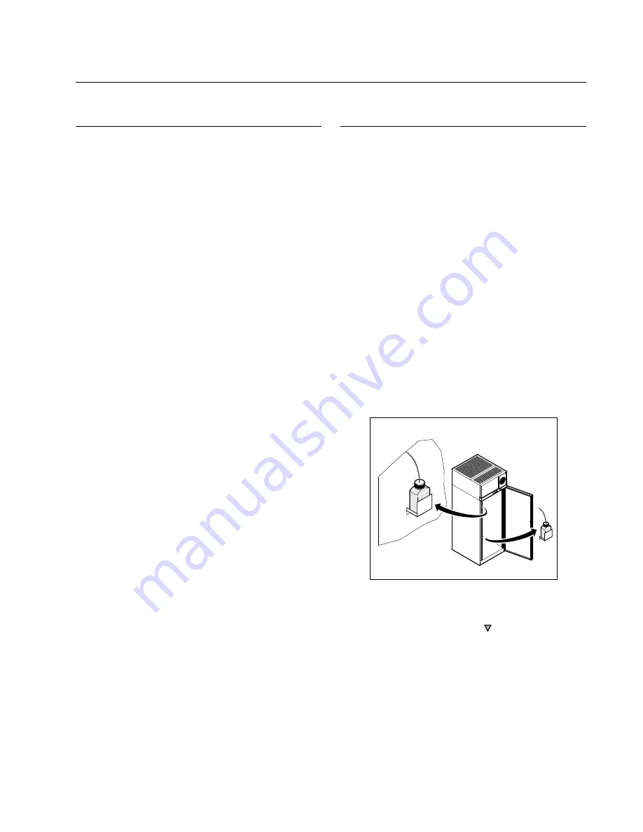
Sensor Bottles

Cabinet temperature is measured by probes inserted in sensor 

bottles. The bottles contain equal portions of glycerine and water 
to simulate blood samples. Keep the sensor bottles completely 
full up to the top of the bottle.

Space Saver models have one factory-installed sensor bottle. In 
Upright models (23 ft

3

 and larger) there are two sensor bottles, 

positioned as shown in Figure 4.

Figure 4.  Sensor Bottles (Upright Models)

The default sensor reading for Upright units is the bottle at the 
top of the cabinet. You can check the temperature in the lower 
sensor bottle by pressing and holding   and 

Scan


simultaneously (refer to Figure 3 on page 4). When you release 
the buttons, the temperature display returns to the upper sensor 
reading. 

Summary of Contents for Jewett JBB1204

Page 1: ...Installation and Operation Manual Thermo Scientific Jewett Blood Bank Refrigerators ...

Page 2: ... 2010 Thermo Fisher Scientific All rights reserved Suva is a registered trademark of DuPont All other trademarks are the property of Thermo Fisher Scientific Inc and its subsidiaries ...

Page 3: ...Hinged Glass Doors Undercounter Models Only 2 4 5 Door Seal 3 4 6 Final Checks 3 5 Drawers 3 5 1 Removing the Drawers 3 5 2 Reinstalling the Drawers 3 5 3 Changing Drawer Slide Position 3 5 4 Control Panel Features 4 6 Control Panel 4 6 1 Display Functions 5 6 2 Programming Functions 5 6 3 Service Parameters 5 7 Operation 6 7 1 Start Up 6 7 2 Product Loading Guidelines 6 7 3 Automatic Defrost 6 8 ...

Page 4: ...9 3 Installing a Remote Alarm Optional 7 9 4 Alarm Test 7 9 4 1 Theory of Operation 7 9 4 2 Alarm Test Procedure 7 10 Chart Recorders 8 10 1 Set Up and Operation 8 10 2 Power Supply 8 10 3 Changing Chart Paper 8 10 4 Calibration Adjustment 8 11 Cleaning 9 11 1 Cleaning the Drawers and Cabinet Interior 9 11 2 Cleaning the Condenser 9 12 Troubleshooting 10 ...

Page 5: ... product warning labels carefully Failure to follow these instructions may cause this product to malfunction which could result in injury or damage Below are important safety precautions that apply to this product Use this product only in the way described in the product literature and in this manual Before using it verify that this product is suitable for its intended use Do not modify system com...

Page 6: ...rloaded power lines Always connect the equipment to a dedicated separate circuit Electrical codes require fuse or circuit breaker protection for branch circuit conductors Use time delay fuses for 12 AWG circuits For all blood bank models the wiring diagram is attached to the back of the cabinet 4 3 Leveling The unit must be level Rotate the leveling screws located under the front corners of the un...

Page 7: ...age the mounting tabs from the slots on the slides Note The drawers fit snugly between the slides Push the back of the drawer from underneath to remove the drawer 3 Raise the back of the drawer almost to a vertical position and disengage the front mounting clips from the slides To remove the drawers on Space Saver models depress the hooks located on both sides of the drawers about 1 3 of the way b...

Page 8: ...of bars illuminated indicates cabinet temperature as follows bulb only 0ºC cold alarm 6 bars 4 8 1 bar 0 8 7 bars 5 6 2 bars 1 6 8 bars 6 4 3 bars 2 4 9 bars 7 2 4 bars 3 2 10 bars 8 warm alarm 5 bars 4 setpoint When cabinet temperature exceeds the warm alarm setpoint the top bar of the thermometer flashes When temperature is lower than the cold alarm setpoint the bulb flashes When you are in prog...

Page 9: ...ss and simultaneously hold for five seconds Excursion values are reset temperature display shows cabinet temperature Alarm test Test by simulating warm alarm conditions key switch must be in alarm mode Press and Scan simultaneously Display and thermometer show simulated cabinet temperature alarms flash and sound as appropriate Alarms clear when test is completed Lower sensor Display lower cabinet ...

Page 10: ...re you load any product 7 3 Automatic Defrost The defrosting process on all models is primarily accomplished by air circulated during off cycle periods Under normal conditions the temperature warm up during defrost is virtually unnoticeable However an occasional 2 C warm up is possible if usage is heavy and ambient conditions are extreme 8 Temperature Control 8 1 Setpoint Control Your individual u...

Page 11: ...ail wire on the alarm The purple and red white wires must be tied together in this application The wiring diagram is attached to the inside of the alarm back cover 9 4 Alarm Test Note It is important to test your alarm system after any maintenance operation or temperature control adjustment 9 4 1 Theory of Operation This test procedure applies to both factory installed built in alarms and optional...

Page 12: ...s low the LED flashes to indicate that the battery needs to be changed 10 3 Changing Chart Paper To change the chart paper complete the following steps 1 Locate the pressure sensitive buttons at the front upper left of the recorder panel 2 Press and hold the change chart button for one second The pen will move off the scale 3 Unscrew the center nut remove the old chart paper and install new chart ...

Page 13: ...ols CAUTION Condensers should be cleaned at least every six months In heavy traffic areas condensers load with dirt more quickly Failure to keep the condenser clean can result in equipment warm up or erratic temperatures CAUTION Never clean near condensers with your fingers Some surfaces are sharp Periodically check the condenser to make sure that it is clean In all models the condenser is located...

Page 14: ... is clean but temperature continues to fluctuate call an authorized service representative Unit warms up Door is open Make sure the door is completely closed Door seal Check the door seal following instructions in Section 4 5 on page 3 Warm product recently loaded in unit Allow ample time to recover from loading warm product Power supply Check for proper voltage to the unit If there is no voltage ...

Page 15: ...iese RoHS Anweisungfallen finden Sie unter www thermo com Conformità WEEE Questo prodotto deve rispondere alla direttiva dell Unione Europea 2002 96EC in merito ai Rifiuti degli Apparecchi Elettrici ed Elettronici WEEE È marcato col seguente simbolo Thermo Fischer Scientific ha stipulato contratti con una o diverse società di riciclaggio smaltimento in ognuno degli Stati Membri Europei Questo prod...

Page 16: ...ve information can be found on the dataplate attached to the equipment If available please provide the date purchased the source of purchase manufacturer or specific agent rep organization and purchase order number IF YOU NEED ASSISTANCE SALES DIVISION Phone 1 866 984 3766 866 9 THERMO LABORATORY PARTS and SERVICE Phone 1 800 438 4851 TECHNICAL SUPPORT Phone 1 800 438 4851 ...

Page 17: ...Thermo Fisher Scientific Inc 275 Aiken Road Asheville NC 28804 United States www thermofisher com 34830H54 Rev A ...

Reviews: