background image

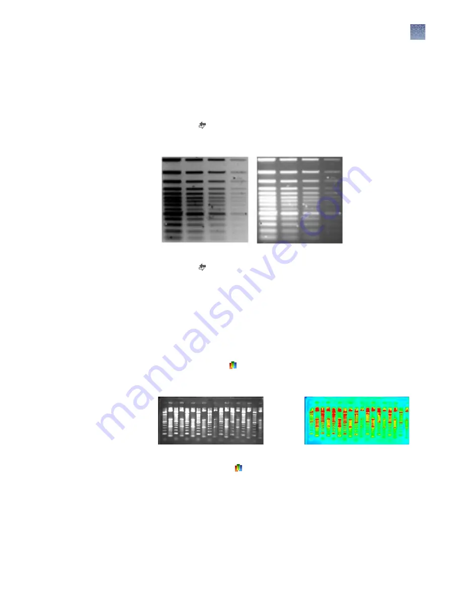
Invert an image

Inverting an image is particularly useful for discriminating between close bands. This
function inverts the color scale of the image (i.e., light areas appear dark and dark
areas appear light, much like for a film negative).

1.

Click 

Invert ( )

 on the control panel.

An inverted version of the image is displayed.

2.

Click 

Invert ( )

 again to revert the image to its original state.

Apply pseudo colors

Pseudo color

 applies a false color palette to the image by applying a color

spectrum, designating "hot" and "cold" regions of the image. Colors are based on
gray scale intensity, where red corresponds to the maximum (hot) and blue
corresponds to the minimum (cold) gray scale levels.

1.

Click 

Pseudo colors ( )

 on the control panel.

An image of the gel with false color is displayed.

2.

Click 

Pseudo Ccolors ( )

 again to revert the image to its original state.

Chapter 3 

GelCapture software

Invert an image

3

E

Gel

 Imager Gel Documentation System User Guide

29

Summary of Contents for E-Gel 4466611

Page 1: ...se Only Not for use in diagnostic procedures E Gel Imager Gel Documentation System USER GUIDE For visualization and documentation of gels Catalog Numbers 4466611and 4466612 Publication Number MAN0004868 Revision A 0 ...

Page 2: ...OR CONSEQUENTIAL DAMAGES IN CONNECTION WITH OR ARISING FROM THIS DOCUMENT INCLUDING YOUR USE OF IT Revision history Pub No MAN0004868 Revision Date Description A 0 24 June 2020 Rebranded updated and transferred to the CCMS Important Licensing Information These products may be covered by one or more Limited Use Label Licenses By use of these products you accept the terms and conditions of all appli...

Page 3: ...ts 14 Installing the E Gel imager gel documentation system 14 Install hardware 14 Install the E Gel Imager Camera Hood and Light Base 15 Using the E Gel Imager gel documentation system 16 Set up the E Gel Imager 16 Launch the GelCapture Software 18 Adjust image settings 18 Define region for image capture 19 Capture and save image 20 Maintenance 20 CHAPTER 3 GelCapture software 21 GelCapture softwa...

Page 4: ... 33 Software installation guidelines 33 Install GelCapture Software 33 Windows XP professional 33 Windows 7 professional 34 Installing the camera driver Windows 7 pro 35 Installing the camera driver Windows 7 professional 35 APPENDIX D The E Gel Imager Band Excision Kit 42 Using the E Gel Imager Band Excision Kit 42 Excise a band from the gel 44 APPENDIX E The White Light Converter 45 Using the Wh...

Page 5: ...quisition functions 55 Using the E Gel imager light base with E Gel iBase device 56 Hardware configuration 56 Using the E Gel Imager Adaptor Base 57 Install hardware 57 Hardware configuration 59 The E Gel Imager iBase Light Diffuser 61 Using the E Gel Imager iBase Light Diffuser 61 APPENDIX I Safety 63 Safety features 63 Safety requirements 63 Chemical safety 64 Biological hazard safety 65 Documen...

Page 6: ...ted to GelQuant Express Software for data analysis Features Small footprint to conserve benchtop space Base units with blue light transillumination avoid the risks associated with UV transillumination Sensors permit illumination only when the E Gel Imager Camera Hood is properly positioned over the E Gel Imager Light Base unit Extended detection feature enables viewing precise images of high and l...

Page 7: ...UV Light Base 4466611 E Gel Imager with E Gel Imager Blue Light Base 4466612 Components The contents of the E Gel Imager Gel Documentation System are listed in the following table Component Cat No 4466611 Cat No 4466612 E Gel Imager Camera Hood Kit Camera Hood Camera Hood USB 2 0 cable E Gel Imager Light Diffuser E Gel Imager Universal Filter GelCapture Imaging Software and GelQuant Express Quanti...

Page 8: ...ger Band Excision Kit 4466605 1 E Gel imager universal filter Components Cat No Quantity E Gel Imager Universal Filter 4466606 1 E Gel imager Qdot 625 filter Components Cat No Quantity E Gel Imager Qdot 625 Filter 4466607 1 E Gel imager UV SYBR filter Components Cat No Quantity E Gel Imager UV SYBR Filter 4466608 1 GelQuant express software activation dongle Components Cat No Quantity GelQuant Exp...

Page 9: ...m in height The base unit provides transillumination for visualization of the gel Front view camera hood on light base Rear view camera hood on light base 1 3 4 1 Camera hood ON OFF power switch 2 USB port 3 Emission filter 4 Light base ON OFF power switch 5 Light base power port 6 iBase power cable port 2 3 6 5 Chapter 1 Product information Description of parts 1 E Gel Imager Gel Documentation Sy...

Page 10: ...apture Software in order to operate Image settings can be adjusted using the software or manually using the dials on the camera hood 1 2 3 5 4 1 ON OFF power switch 2 Manual iris dial 3 Manual focus dial 4 Filter tray 5 Emission filter Chapter 1 Product information Description of parts 1 10 E Gel Imager Gel Documentation System User Guide ...

Page 11: ...s of each E Gel Imager Base are 30 5 cm length 21 cm width E Gel Imager Blue Light Base The E Gel Imager Blue Light Base is used to visualize gels stained with SYBR dyes This light base can be used to visualize E Gel pre cast agarose gels An automatic shut off switch turns off the transilluminator after 20 minutes 1 3 2 4 1 Glass plate 2 Bordered wall 3 Power switch 4 Wall breech Chapter 1 Product...

Page 12: ...s light base can be used to visualize E Gel precast agarose gels An automatic shut off switch turns off the transilluminator after 10 minutes 1 3 4 2 1 Glass plate 2 Bordered wall 3 Power switch 4 Wall breech Chapter 1 Product information Description of parts 1 12 E Gel Imager Gel Documentation System User Guide ...

Page 13: ...sal Filter is an orange filter for general use Applications include ethidium bromide stained gels that are used with UV transillumination or SYBR dyes with blue light transillumination E Gel Imager UV SYBR Filter E Gel Imager UV SYBR Filter is a green filter for visualizing SYBR dyes with UV transillumination E Gel Imager Qdot 625 Filter E Gel Imager Qdot 625 Filter is a red filter for visualizing...

Page 14: ...1 1 Installing the E Gel imager gel documentation system The installation procedure for the E Gel Imager Gel Documentation System can be completed in four steps as outlined below Install hardware E Gel Imager Light Base See page 14 Install GelCapture Software Windows 7 Professional See page 34 Windows 10 Professional Install GelCapture from the CD Install GelQuant Express Software GelQuant Express...

Page 15: ...ll plug to an electrical socket 3 Plug the USB 2 0 cable into the camera USB port of the camera hood and connect the other end into the USB 2 0 port of your computer 1 2 3 4 5 6 1 E Gel Imager Light Base 2 Universal 12 V power cord 3 Electrical socket 4 E Gel Imager Camera Hood 5 USB 2 0 cable 6 Computer Chapter 2 Methods Install hardware 2 E Gel Imager Gel Documentation System User Guide 15 ...

Page 16: ...e E Gel Imager 1 Ensure that the type of filter in the filter tray is appropriate for the type of stain being used in your gel sample If the filter does not provide the best image possible it may be necessary to test imaging with another type of filter see Colored emission filters on page 13 for more information 2 Remove the E Gel Imager Camera Hood from the E Gel Imager Base 3 Place the gel in th...

Page 17: ...mera on 6 Turn the E Gel Imager Base on 7 When the camera and transilluminator are turned on the image of the gel is displayed on the Live mode screen in real time Chapter 2 Methods Using the E Gel Imager gel documentation system 2 E Gel Imager Gel Documentation System User Guide 17 ...

Page 18: ...ine adjustment of the image to attain an image that is clear sharp and bright using either the minus or plus buttons or sliding the gauges for each setting see page 22 Exposure time can be set from 0 14 1 0 seconds Increased exposure allows weaker signals that are not visible at a lower exposure time to be visible Sensitivity adjusts the degree of signal detection The maximum exposure time is auto...

Page 19: ...of interest to define the region of the gel that you wish to image 2 A green rectangular frame pops up around the image Drag the edges of the green rectangle with your cursor to select your area of interest AOI Chapter 2 Methods Using the E Gel Imager gel documentation system 2 E Gel Imager Gel Documentation System User Guide 19 ...

Page 20: ...select BMP or JPEG 6 Browse to the location where you want the image to be saved and enter a name for the image then click Save Maintenance To keep the E Gel Imager in good working order observe the following guidelines The glass plate of the E Gel Imager Light Base must be cleaned every time a sample is removed Use a soft non abrasive lint free cloth To clean the E Gel Imager and Light Base surfa...

Page 21: ...or analysis The friendly GUI lets you perform common actions with a single click of a button or icon Home screen The Home screen appears upon launching the GelCapture software 1 4 5 2 3 4 1 Select UV Light Base 2 Select Blue Light Base 3 Select Adaptor Base 4 Select hardware configuration to access the Live mode screen 5 Open image file to access the Edit mode screen 3 E Gel Imager Gel Documentati...

Page 22: ...d detection on page 27 5 Brightness The slide gauge is used to adjust image brightness 6 Area of interest Allows tools to be used in selected regions of the image in Live mode or for a saved image 7 Overexposure See Correct overexposure on page 28 8 Change Used to return to Home screen to change hardware configuration 9 Control panel See Description of live mode control panel tools on page 23 10 P...

Page 23: ...Prints an image Exports an image as BMP or JPEG file Shortcut to the analysis software Go to Edit mode available in both single capture mode and multiple image acquisition mode Captures multiple images over a set period of time at designated intervals Chapter 3 GelCapture software Description of live mode control panel tools 3 E Gel Imager Gel Documentation System User Guide 23 ...

Page 24: ...rn to Home screen 8 File Open File menu see page 26 9 Preferences Open Preferences menu see page 26 10 Show over exposure See Correct overexposure on page 28 11 Value The gray scale value of the pixel being examined 12 Y The position of the pixel being examined on the y axis 13 X The position of the pixel being examined on the x axis 14 Histogram See About the histogram on page 27 15 Control panel...

Page 25: ...Edit mode This increases the contrast of the image and can be used to reveal low concentration bands in the gel image Creates an inverted color version of the image The function changes the image color from black to white and vice versa Shows the image in using a color spectrum Restores original image back to original grey scale values It is the opposite of Auto contrast and does not affect Invert...

Page 26: ...e elsewhere available in Edit Mode only Exit Exit software Preferences menu Area of interest Selects a specific area to work within the image Full screen Full screen view Click the ESC button to exit full screen view Pseudo color Shows the image in using a color spectrum Invert Creates an inverted color version of the image The function changes the image color from black to white and vice versa Ov...

Page 27: ...by stretching the signal This can be achieved by dragging the cursor at the left and right margins of the histogram and moving them towards the center 1 2 1 Left cursor 2 Right cursor Perform extended detection This tool is used to increase dynamic range for optimal capture of images in gels that contain bands of both high and low intensity 1 View the gel in the Live mode screen 2 Click the Extend...

Page 28: ...camera for example reducing exposure time sensitivity and or brightness The GelCapture overexposure tool automatically displays overexposed saturated areas in red in a given image 3 After overexposure has been corrected click Save Apply auto contrast This function increases the contrast of the image and helps to reveal low concentration bands in the gel image 1 Click Auto contrast in the control p...

Page 29: ...iginal state Apply pseudo colors Pseudo color applies a false color palette to the image by applying a color spectrum designating hot and cold regions of the image Colors are based on gray scale intensity where red corresponds to the maximum hot and blue corresponds to the minimum cold gray scale levels 1 Click Pseudo colors on the control panel An image of the gel with false color is displayed 2 ...

Page 30: ...d properly connected to an electrical outlet Loose internal power supply button cables Contact technical support The camera is not recognized Camera not switched on Ensure the camera is switched on Software was turned on prior to setting up the device Make sure the light base and imager hood are set up and switched on before launching the software Cables not connected properly Ensure that the came...

Page 31: ...technical support Duration of E Gel Safe Imager transillumination too short E Gel Safe Imager transilluminator switched on with short press 30 second transillumination Press the button on the E Gel Safe Imager for 2 seconds The transilluminator turns on for 5 minutes before automatic shutoff Appendix A Troubleshooting Apply pseudo colors A E Gel Imager Gel Documentation System User Guide 31 ...

Page 32: ...th the E Gel Imager Camera Hood 100 240 VAC 50 60 Hz 0 6 A E Gel Imager Light Base UV or Blue Light Condition Description Viewing surface dimensions 42 mm 83 mm Case dimensions 11 9 cm height 30 5 cm length 21 cm width Electrical Requirements 100 240VAC 50 60Hz 0 6A Temperature Ambient 5 C to 40 C Adaptor Specifications Use only the UL Listed adaptor supplied with the E Gel Imager Light Base 90 26...

Page 33: ...ministrator privileges for installation only Verify that you are logged in as an Administrator before starting installation If you do not have Administrator privileges contact your IT department for help Change PC power setting to Never Hibernate Make sure that the PC is not connected to the E Gel Imager when installing the GelCapture software Install GelCapture software before turning on the E Ge...

Page 34: ... Select Allow I trust this program I know where it s from or I ve used it before to allow the program to run 3 Follow the instructions provided by the installation wizard 4 Once installation is complete click Finish to exit Setup Appendix C Software installation Install GelCapture Software C 34 E Gel Imager Gel Documentation System User Guide ...

Page 35: ... sure that the GelCapture software for Windows 7 Professional is installed on the computer Windows 7 professional on page 34 1 Go to Windows Control Panel by clicking Start Settings Control Panel 2 Open the Hardware and Sound settings Appendix C Software installation Installing the camera driver Windows 7 pro C E Gel Imager Gel Documentation System User Guide 35 ...

Page 36: ...2 0 cable from the PC to the E Gel Imager and turn the E Gel Imager camera on The Device Manager should recognize the new device connection and alert you Appendix C Software installation Installing the camera driver Windows 7 pro C 36 E Gel Imager Gel Documentation System User Guide ...

Page 37: ... and select Update Driver Software 6 In the Update Driver Software window select Browse my computer for driver software Appendix C Software installation Installing the camera driver Windows 7 pro C E Gel Imager Gel Documentation System User Guide 37 ...

Page 38: ... from a list of device drivers on my computer 8 Choose E Gel Imager USB2 and click Have Disk Appendix C Software installation Installing the camera driver Windows 7 pro C 38 E Gel Imager Gel Documentation System User Guide ...

Page 39: ...Browse to the following location My computer Local Disc C Program Files EGel Imager GelCapture drivers EGel and click Open Appendix C Software installation Installing the camera driver Windows 7 pro C E Gel Imager Gel Documentation System User Guide 39 ...

Page 40: ...Choose EGel Imager from the E Gel Imager folder and click Open 12 Click OK Appendix C Software installation Installing the camera driver Windows 7 pro C 40 E Gel Imager Gel Documentation System User Guide ...

Page 41: ...cessful update window will be displayed Click Close 15 Close the Device Manager and Control Panel windows The E Gel Imager camera driver is now installed and ready for use Appendix C Software installation Installing the camera driver Windows 7 pro C E Gel Imager Gel Documentation System User Guide 41 ...

Page 42: ...your eyes from intense blue light exposure Wear gloves when handling gels WARNING The Safe Imager Viewing Glasses do not protect from UV light Do not use the Safe Imager Viewing Glasses with the UV light base When using UV light wear appropriate eyewear that will protect eyes from UV light When cutting bands from the E Gel Imager UV Light Base use the appropriate safety equipment to protect yourse...

Page 43: ...er Light Base from scratches when cutting gel bands 3 E Gel Imager Light Base Not included with E Gel Imager Band Excision Kit 4 Safe Imager Viewing Glasses Protects the eyes from intense blue light and allow bands to be viewed available separately as Cat No S37103 Appendix D The E Gel Imager Band Excision Kit Using the E Gel Imager Band Excision Kit D E Gel Imager Gel Documentation System User Gu...

Page 44: ... on top of the sensor and power on the E Gel Imager Light Base 4 Use a clean knife or scalpel to cut bands from the gel 5 After cutting the bands remove the magnet then transfer the excised bands from the plate to the light base 6 Place the camera hood back on top of the light base 7 Press the camera ON OFF button to view the gel bands Appendix D The E Gel Imager Band Excision Kit Using the E Gel ...

Page 45: ...ed with visible dyes 1 2 1 White Light Converter 2 E Gel Imager Light Base Not included with E Gel Imager Band Excision Kit View a gel with the white light converter 1 Remove the E Gel Imager Camera Hood 2 Place the White Light Converter on the E Gel Imager Light Base 3 Place your gel on top of the White Light Converter 4 Place the E Gel Imager Camera Hood back on top of the Light Base E E Gel Ima...

Page 46: ...ample turn the unit OFF remove the Tower remove the sample from the Light Base and clean the Light Base with water and ethanol Then place the new sample on the Light Base Appendix E The White Light Converter Using the White Light Converter E 46 E Gel Imager Gel Documentation System User Guide ...

Page 47: ... filter Cat No 4466606 E Gel Imager Qdot 625 Filter 1 filter Cat No 4466607 E Gel Imager Qdot UV SYBR Filter 1 filter Cat No 4466608 GelQuant Express Software Activation Dongle 1 each Cat No 4466610 E Gel Devices E Gel Safe Imager Real Time Transilluminator 1 unit Cat No G6500 E Gel Power Snap Electrophoresis System E Gel Power Snap Electrophoresis Device 1 unit G8100 E Gel Power Snap Electrophore...

Page 48: ...olt EX Gel 4 10 Pak G401004 E Gel 1 2 with SYBR Safe 18 Pak G521801 E Gel EX 2 Agarose Gels 20 gels Cat No G402002 E Gel EX 4 Agarose Gels 10 gels Cat No G401004 Staining and detection Unless otherwise indicated all materials are available through thermofisher com MLS indicates that the material is available from fisherscientific com or another major laboratory supplier Item Amount Source SYBR Gre...

Page 49: ... documentation This symbol indicates that the device operates on alternative current This symbol indicates that the device is protected by double reinforced insulation The WEEE Waste Electrical and Electronic Equipment symbol indicates that this product should not be disposed of in unsorted municipal waste Follow local municipal waste ordinances for proper disposal provisions to reduce the environ...

Page 50: ...r Base is used with the E Gel Safe Imager Transilluminator to to visualize gels stained with SYBR dyes The E Gel Imager Adaptor Base can also be used with the E Gel iBase Device to visualize of E Gel pre cast agarose gels 3 2 1 1 Well 2 Bordered wall 3 Wall breech H 50 E Gel Imager Gel Documentation System User Guide ...

Page 51: ...e Correct overexposure on page 28 5 Change Used to return to Home screen to change hardware configuration 6 Capture a new image Used to return to Live mode screen Available only when image capture is stopped 7 Stop Used to stop image acquisition Available only during image capture 8 Progress bar Amount of time remaining for multiple image capture 9 Unselect all To unselect all images 10 Main menu ...

Page 52: ...uence 7 Brightness The brightness used to capture the image 8 Main menu tools See descriptions on page 26 9 Overexposure See Correct overexposure on page 28 10 Value The gray scale value of the pixel being examined 11 Y The position of the pixel being examined on the y axis 12 X The position of the pixel being examined on the x axis 13 Histogram See About the histogram on page 27 14 Control panel ...

Page 53: ...ured with the new settings 5 Click Start to start the image series capturing process 6 A new screen appears that displays the progress of the image capture in a series of thumbnail images Double clicking on any thumbnail image brings you to the Multiple image acquisition edit mode screen for that image see page 52 5 5 5 5 1 2 3 4 1 Image already captured 2 Image currently being captured 3 Image cu...

Page 54: ...the acquisition process is completed or acquisition is aborted the Capture a new image button appears on the screen Appendix H Products no longer supported The E Gel Imager iBase Light Diffuser H 54 E Gel Imager Gel Documentation System User Guide ...

Page 55: ...f previous and new information The background for a second image is based on information from both the first and second images although the second image was captured with the same exposure time as the first image in the series Appendix H Products no longer supported The E Gel Imager iBase Light Diffuser H E Gel Imager Gel Documentation System User Guide 55 ...

Page 56: ... affix the E Gel Imager iBase Light Diffuser to the underside of the E Gel iBase Device when using the E Gel iBase Device with the E Gel Imager System see Attach the E Gel Imager iBase Light Diffuser on page 61 1 2 3 1 E Gel iBase 2 DC connector cable 3 E Gel Imager Light Base Appendix H Products no longer supported Using the E Gel imager light base with E Gel iBase device H 56 E Gel Imager Gel Do...

Page 57: ...e 3 Connect the Universal 12 V power port at the rear of the E Gel Imager Light Base 4 The E Gel iBase Device is now ready for use with the E Gel Imager Using the E Gel Imager Adaptor Base Install hardware Install the hardware for the E Gel Imager Camera Hood and E Gel Imager Adaptor Base as described in the following section To install the E Gel Imager Light Base see Install hardware on page 14 A...

Page 58: ...nto the camera USB port of the camera hood and connect the other end into the USB 2 0 port of your computer 1 3 4 5 6 2 1 E Gel Imager Adaptor Base 2 48 V power supply from the E Gel iBase Device or the E Gel Safe Imager Transilluminator 3 Electrical socket 4 E Gel Imager Camera Hood 5 USB 2 0 cable 6 Computer Appendix H Products no longer supported Using the E Gel Imager Adaptor Base H 58 E Gel I...

Page 59: ...ast agarose gels 4 1 2 3 5 1 E Gel iBase 2 E Gel Safe Imager 3 E Gel Imager Adaptor Base 4 DC connector cable 5 E Gel Safe Imager power cable IMPORTANT When using the E Gel Safe Imager to provide transillumination for imaging ensure to push the red button on the E Gel Safe Imager for 2 seconds to extend the duration of transillumination to 5 minutes Appendix H Products no longer supported Using th...

Page 60: ... into the well of the E Gel Imager Adaptor Base 4 Connect the iBase Safe Imager power supply cable to the 48 V power port at the rear of the E Gel Imager Adaptor Base 5 The E Gel iBase Device is now ready for use with the E Gel Imager System 6 Press the ON OFF power button to power on the E Gel Safe Imager 1 1 E Gel Safe Imager ON button Appendix H Products no longer supported Using the E Gel Imag...

Page 61: ...r side 1 2 1 2 3 1 Velcro strip for E Gel iBase Device 2 Velcro strip on E Gel Imager iBase Light Diffuser 3 E Gel Imager iBase Light Diffuser Attach the E Gel Imager iBase Light Diffuser 1 Remove the velcro strips from the diffuser then peel off the brown adhesive backing 2 Attach the velcro strips to the back of the E Gel iBase Device then press firmly to set the strips in place Note Do not remo...

Page 62: ...ome in contact with the velcro strips on the E Gel iBase Device 5 The E Gel iBase Device is now ready to be used with the E Gel Imager 6 To remove the diffuser from the E Gel iBase Device gently separate the velcro strips Appendix H Products no longer supported The E Gel Imager iBase Light Diffuser H 62 E Gel Imager Gel Documentation System User Guide ...

Page 63: ...ety features An internal sensor prevents accidental electrocution when the tower is lifted off the base by automatic circuit cut out This system has automatic shut down when not in use for more than 20 minutes Safety requirements Verify that all devices are turned off before making any connections Do not block the ventilation openings of any parts of the E Gel Imager unit or of its sub assemblies ...

Page 64: ...example safety glasses gloves or protective clothing Minimize the inhalation of chemicals Do not leave chemical containers open Use only with adequate ventilation for example fume hood Check regularly for chemical leaks or spills If a leak or spill occurs follow the manufacturer s cleanup procedures as recommended in the SDS Handle chemical wastes in a fume hood Ensure use of primary and secondary...

Page 65: ...quirements before working with potentially biohazardous materials Follow all applicable local state provincial and or national regulations The following references provide general guidelines when handling biological samples in laboratory environment U S Department of Health and Human Services Biosafety in Microbiological and Biomedical Laboratories BMBL 5th Edition HHS Publication No CDC 21 1112 R...

Page 66: ... protocols Certificates of Analysis Safety Data Sheets SDSs also known as MSDSs Note For SDSs for reagents and chemicals from other manufacturers contact the manufacturer Limited product warranty Life Technologies Corporation and or its affiliate s warrant their products as set forth in the Life Technologies General Terms and Conditions of Sale at www thermofisher com us en home global terms and c...

Page 67: ......

Page 68: ...E Gel Imager_UG_MAN0004868 v1 GUID 93F6BB57 826D 47E1 86B2 8581C36DE233 2018 09 13 13 29 35 en 15 24 59 097 04 00 thermofisher com support thermofisher com askaquestion thermofisher com 16 July 2020 ...

Reviews: