background image

4-2

12A Water Still

Thermo Scientific

Section 4

Assembly

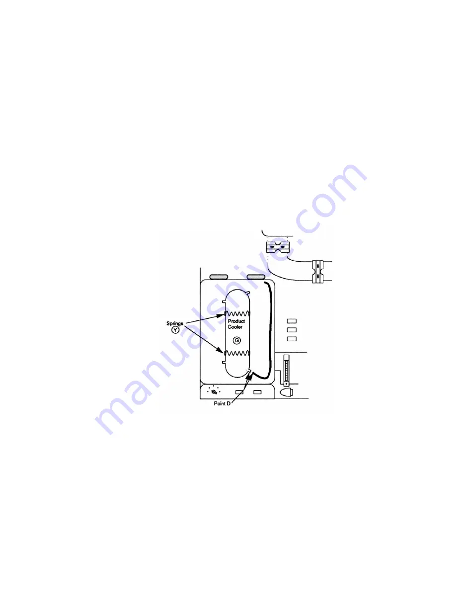
Refer to Figure 4-2 for the following steps:

5.  Remove the two (2) springs Y from the product cooler G and remove

cooler from cabinet.

6.  Remove tape from the condenser outlets. Allow the salt used as

packing to flow into the plastic bag around the condenser. Discard the
bag and salt. Rinse the remaining salt residue from the condenser.

7.  Re-install product cooler in cabinet with the two (2) springs Y. Outlet

on upper left hand side of cooler should be lined up with hole in
cabinet .

8.  Remove tape from 3/8" I.D. vinyl hose and connect to lower right

product cooler outlet Point D (Figure 4-2). Use warm water for ease of
assembly.

Refer to Figures 4-3 and 4-4 for the following steps.

9.  In the following steps, glass tubing will be assembled using Teflon

connectors S. The Teflon connectors have been factory installed on one
end of the glass tubing. Tubing has been numbered for ease of
identification. To ease assembly, use warm water on glassware and
Teflon connectors.

Figure 4-2. 

Cooler Setup

Summary of Contents for 678 Series

Page 1: ...MEGA PURE 12A Water Still Series 678 Operating Manual and Parts List 927793 7006753 Rev 3 Visit us online to register your warranty www thermoscientific com warranty ...

Page 2: ...12 Removed 208V heater part number as unavailable pg 9 1 ccs 1 27447 6 30 11 Revised set up operation and added cartridge numbers ccs 0 4 12 10 Transfer to Marietta was 927793 6 18 08 ccs REV ECR ECN DATE DESCRIPTION By Preface 12A Water Still i Models included in this manual Models Voltage A442012 6754 208V A442011 6753 240V ...

Page 3: ...ments and maintenance must be performed by qualified service personnel s Material in this manual is for information purposes only The contents and the product it describes are subject to change without notice Thermo Fisher Scientific makes no representations or warranties with respect to this manual In no event shall Thermo be held liable for any damages direct or incidental arising out of or rela...

Page 4: ...quipment that has been put on the market after 13 August 2005 This product is required to comply with the European Union s Waste Electrical Electronic Equipment WEEE Directive 2002 96 EC It is marked with the WEEE symbol Thermo Fisher Scientific has contracted with one or more recycling disposal companies in each EU Member State European Country and this product should be disposed of or recycled t...

Page 5: ... fill your needs for spare or replacement parts or provide you with on site service We can also provide you with a quotation on our Extended Warranty for your Thermo Scientific products Whatever Thermo Scientific products you need or use we will be happy to discuss your applications If you are experiencing technical problems working together we will help you locate the problem and chances are corr...

Page 6: ...ils 4 5 Installation 5 1 Bench Mounting 5 1 Wall Mount 5 1 Operation 6 1 High Temperature Cutoff Switch 6 3 Demineralizer Cartridge Changing 6 3 Maintenance and Servicing 7 1 Troubleshooting 8 1 Electrical 8 3 Replacement Parts 9 1 Electrical Replacement Parts 9 2 Diagrams 10 1 Ordering Procedures 10 2 Section 1 Section 2 Section 3 Section 4 Section 5 Section 6 Section 8 Section 7 Section 9 Sectio...

Page 7: ......

Page 8: ...ure to properly connect may create a fire or shock hazard 4 Do not mount your MEGA PURE 12A Water Still directly over equipment that requires electrical service Routine maintenance of this unit may involve water spillage and subsequent electrical shock hazard if improperly located 5 For continued protection against possible fire hazard replace fuses only with the same type and rating of fuse 6 Do ...

Page 9: ...ety instructions on labels of chemical containers and Material Safety Data Sheets M S D S 8 Refer servicing to qualified personnel To ensure safe mounting Wall composition and construction as well as fastener type must be considered when mounting this unit The mounting surface and fasteners selected must be capable of supporting a minimum of 150 lbs inadequate support and or fasteners may result i...

Page 10: ...ete unit or it can also be connected to the Thermo Scientific Automatic Collection System for complete automatic operation The MEGA PURE 12A is rated at 240V 50 60 Hz 10 000 watts single phase It is also available in 208V Changing the unit for use on either 240V or 208V operation requires only replacing the four Vycor immersion heaters with heaters having the required voltage rating The electrical...

Page 11: ...ker box as shown in Figure 1 2 Warning Do not connect unit to power source until instructed to do so s Warning Use a properly grounded electrical outlet of correct voltage and current handling capacity s The Vycor immersion heaters will be labeled either 208V or 240V according to your order The 240 volt heaters may be used at 208V 220V 230V or 240V but at the lower voltages there will be some redu...

Page 12: ... Section 4 OPTION 2 An untreated cold water supply plus a source of RO demineralized or previously distilled water The untreated supply must be capable of pro viding a minimum of 26 gallons per hour at a pressure of 20 100 psi and be located within 4 feet of the water still The treated supply must be capable of providing 3 4 gallons per hour and be located within 4 feet of the water still You must...

Page 13: ......

Page 14: ...amage Identify any broken or damaged parts and report them to your dealer immediately 4 Using diagonal cutting pliers cut and remove the seven 7 plastic shipping ties Do not remove the tape from the hoses inside the cabinet until instructed to do so The shipping tie locations are Two 2 on the condenser F two 2 on the boiler A two 2 on the product cooler G and one 1 on the trap E Refer to Figure 3 ...

Page 15: ...3 2 12A Water Still Thermo Scientific Section 3 Unpacking Fig 3 1 Component Location 50K 150K 300K 500K 1meg purge High purity Change cartridge Fig 3 1 Component Location Fig 3 2 Control Panel ...

Page 16: ... the condenser F up in its bracket This will tilt trap as shown in Figure 4 1 3 Tighten coupling R using 7 16 wrench Coupling should be just tight enough to prevent rotation with moderate hand pressure 4 In the following steps use warm water on connections for ease of assembly a Remove tape from 3 8 I D vinyl hose and connect to upper right condenser outlet at Point A Figure 4 1 b Remove tape from...

Page 17: ...n cabinet with the two 2 springs Y Outlet on upper left hand side of cooler should be lined up with hole in cabinet 8 Remove tape from 3 8 I D vinyl hose and connect to lower right product cooler outlet Point D Figure 4 2 Use warm water for ease of assembly Refer to Figures 4 3 and 4 4 for the following steps 9 In the following steps glass tubing will be assembled using Teflon connectors S The Tef...

Page 18: ...4 4 c Connect socket joint End 3 to the lower condenser F outlet using a 18 A Thomas clamp W from the parts box Do not overtighten clamp See Point 3 on Figure 4 4 Product Cooler may be adjusted up or down as required d Locate product outlet tube J in parts box Route through cabinet holes as shown in Figure 4 3 Connect end labeled 4 to the upper left tubulation on the product cooler G See Point 4 o...

Page 19: ...gs and cords through the 3 hole above the boiler A then back through the hole below the control box M Plug one plug into each heater receptacle on bottom of control box Plugs are twist lock type and require clockwise turn to lock in place Caution Do not remove the Teflon sleeve covering the molded rubber sleeve on heater element s Refer to Figure 4 5 for the following steps 13 Remove tape from all...

Page 20: ...e Figure 4 6 a Locate T connector 1 and threaded connector 2 in the parts box b Connect the T connector 1 to the two high pressure hoses T These hoses connect to solenoid valves N and may be shortened to a suitable length Hand tighten nuts on T connector c Thread connector 2 into your water supply and tighten Connect length of high pressure hose between T connector 1 and threaded connector 2 Hand ...

Page 21: ... as shown in Figure 4 8 Be sure labels on cartridges are upright and firmly seat cartridges against gaskets in holders by tightening knobs above holders Figure 4 7 shows two high capacity cartridges in place 3 Tighten cartridge drain clamps located behind lower cartridge holders Clamps are accessible through the left side of the cabinet 4 To connect your MEGA PURE 12A Water Still to the Automatic ...

Page 22: ...12A Water Still 4 7 Thermo Scientific Section 4 Assembly Figure 4 7 Locations Figure 4 8 Installed ...

Page 23: ......

Page 24: ...astener type must be considered when mounting this unit The mounting surface and fasteners selected must be capable of supporting a minimum of 150 lbs inadequate support and or fasteners may result in damage to mounting surface and or equipment If unsure of mounting surface composition condition and construction or correct fasteners consult your building maintenance group or contractor s The MP 12...

Page 25: ...5 2 12A Water Still Thermo Scientific Section 5 Installation Figure 5 1 Connections with Dimensions ...

Page 26: ...constant level chamber B 7 Push OFF switch and open drain plug V on bottom of boiler A When boiler is empty close drain plug V 8 Push WATER switch and allow boiler to fill Set right flowmeter to approximately 25 GPH 9 Set purity selector on demineralizer control to 50K ohms Note Only 50K and 150K ohm settings are recommended for the standard demineralizer cartridges higher purity feedwater setting...

Page 27: ...der most feedwater conditions the 450 cc min flow rate will provide greater than 60 C at the condenser vent Very cold feedwater may require slightly less than 450 cc min to maintain vent temperature above 60 C To optimize product water purity use a thermometer to verify vent temperature to 60 C s 12 Your MEGA PURE 12A Water Still should now be operational Run the still for 4 5 hours to cleanse its...

Page 28: ...low meters should not need adjustment Your MEGA PURE 12A Water Still is protected against overheating by two thermal switches located in the black V shaped bracket at the left hand side of the boiler that will shut off both the water supply and power to the heaters when activated Always allow the unit to cool completely 5 15 minutes before resuming operation Cool water on hot glass could cause boi...

Page 29: ......

Page 30: ...ing as acid spattering may occur s If cleaning is desired after extended operation or boiler scale is visible due to bypassing the deionizer system the unit should be cleaned with a hydrochloric acid solution This is accomplished as follows 1 Push unit OFF switch 2 Disconnect the product outlet tube J from the product cooler G at Point 4 see Figure 7 Connect 4 length of 3 8 I D vinyl tubing from p...

Page 31: ...l If scale remains that the 10 hydrochloric solution will not remove rinse boiler three times with feedwater fill and drain Add 800 ml of 6 NaOH to boiler and let stand for 30 minutes Flush boiler several times after draining 7 Carefully drain the unit remove clamp from overflow tube and refill with fresh water and operate for 30 minutes Turn still off drain boiler and refill with fresh water Remo...

Page 32: ...iler indicates that the demineralizer is not being used or the car tridges need changing Clean boiler per cleaning instructions Scale should not be allowed to accumulate as heaters may be damaged Heater Failure Heater failure due to scale buildup or alkali attack will not be replaced under warranty Short life on Vycor immersion heaters can usually be attributed to use of water pretreated with NaCl...

Page 33: ...accordingly Also see Steam at Condenser Vent as excess steam at this point will reduce output Leaking around demineralizer cartridges Improperly seated gaskets or loose cartridge Check system to be sure cartridge is seated on gaskets and that securing knob has been screwed down tight If leak persists replace gaskets Premature cartridge failure NaCl regenerated water softeners The D400499 cartridge...

Page 34: ...rical Still Troubleshooting Problem Causes Solution Heaters and water will not stay on Hi temp cut off switch open Remove control box and black V shaped switch bracket and replace both switches Heater not working Heater burned out Replace heater unit can be operated on less than four heaters Water will not come on but light works Solenoid valve not working Check plug for connection Replace solenoi...

Page 35: ... light burned out Check replace Still on with red light on demineralizer Relay contacts closed Input jack not plugged in Check and replace relay Check and reconnect jack Both lights on or good lights will not light or erratic light operation Printed circuit board Replace Automatic Collection System Troubleshooting Problem Causes Solution Will not turn still on or off as it should Float stuck Remov...

Page 36: ...r A Boiler 401934 B Constant Level Chamber 401923 C Vycor Immersion Heater 240V 2500W 740883 D 90 x 3 Elbow 401924 E Steam Trap 401925 F Condenser 401926 G Product Cooler 401927 H Boiler Fill Tube Cooler to Connector 401928 I Boiler Fill Tube Connector to Boiler 401929 J Product Outlet Tube 401931 K Condenser Cooler Tube Condenser to Connector 401932 L Condenser Cooler Tube Connector to Cooler 401...

Page 37: ...ate switch 410916 N S Off Switch 410917 N S R 1 Relay 410473 N S R 2 3 Relay 410552 N S Bridge Rectifier 410471 N S Transformer 410472 N S High Temp Cut Off Switch 410137 N S Fuse 5 amp FZX16 Demineralizer Control Box Item Description Part Number O Complete Control Box 440379 N S Conductivity Electrode 441938 N S Red Lamp Assembly 410122 N S Green Lamp Assembly 410123 N S Fuse 410124 N S DI ACS Ja...

Page 38: ...ment Parts Item Description Part Number P Flowmeter 0 600 cc min 410152 Q Flowmeter 0 30 gal hr 400485 R 3 Coupling 409170 S Glass Center Teflon 7 16 I D 401416 T Tubing Hi Press 1 4 O D x 5 Long 410126 U Plastic Hose Fitting Assortment 410447 W 18 A Thomas Clamp 410141 X Boiler or Trap Spring 410528 Y Condenser or Product Cooler Spring 410918 Z Constant Level Chamber Spring 410211 AA Boiler Fill ...

Page 39: ......

Page 40: ... Section 10 Diagrams 3515 Automatic Collection System Optional Notes 1 Control box diagrams are illustrated with no power applied 2 When control jacks from demineralizer and ASC Disconnect these jacks to isolate problems for troubleshooting ...

Page 41: ...erein may be ordered from the Thermo Scientific dealer from whom you purchased this unit or can be obtained promptly from the factory When service or replacement parts are needed check first with your dealer If the dealer cannot process your request then contact our Technical Services Department Prior to returning any materials please contact our Technical Services Department for a Return Material...

Page 42: ...cle J6 Water Level Jack J7 Demineralizer Jack J8 Demineralizer Receptacle K1 Relay with Aux Switch K2 Relay with Aux Switch K3 Relay L1 Dual Solenoid Valve Assembly Ref No Description S1 Switch Off S2 Switch Operate S3 Switch Water S4 Switch Thermal Open 170 5 F Closed 140 9 F S5 Switch Thermal S6 Rotary Selector Switch T1 Transformer TB1 Terminal Block Part 1 Terminal Block Part 2 TB2 Terminal Bl...

Page 43: ......

Page 44: ...Thermo Fisher Scientific 401 Millcreek Road Marietta Ohio 45750 United States www thermofisher com ...

Reviews: