


35
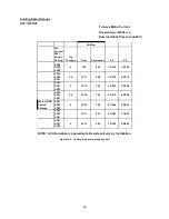
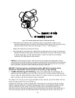
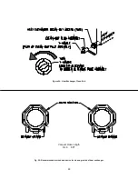
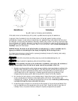
Figure 19: Preliminary Adjustment of Burner Air Band and Air Shutter
i.
When ignition is established, make a preliminary burner air adjustment to attain a clean
combustion flame. Generally, the burner bulk air band should be about 3/16 inch open and the
opening of the burner air shutter set in the range of “2” to “7”, refer to Figure 19.
Replace the inspection cover above the burner.
j.
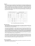
After the appliance is warmed up to a steady state condition (about 15 minutes), the final burner
adjustment should be made using combustion instrumentation for smoke, carbon dioxide (CO2)
or excess oxygen (O2), and flue gas temperature. In order to achieve the most efficient
combustion, the following steps must be taken:
i.
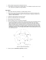
SMOKE:
A smoke sample should be drawn from the heat exchanger flue passageway, which is
covered by the vent terminal. (Remove a large machine screw from the front face of the vent terminal
for direct access to the flue through the opening.) If the first smoke reading is zero (0), close the air
band, or shutter, on the burner until a trace smoke reading is measured.
NOTICE: To achieve proper combustion and the efficiencies listed in sales
brochures, instruments must be used to secure CO2
or O2
readings.
ii.
CARBON DIOXIDE (CO2) OR OXYGEN (O2):
Take a CO2 sample from flue passageway. It is
possible to achieve readings of up to 14% CO2 (or 2% O2 ), but it is better to have a slightly lower
CO2 (or higher O
2
) reading with zero smoke measured. To achieve a lower CO2 reading, open the air
band, or shutter, on the burner until zero smoke is measured.
For example, if a 13% CO2 (or 3.5% O2) is recorded at a trace of smoke, open the air shutter until zero
smoke is measured with a 12% CO
2
(or 4.5% O2).
Adjustment of the burner to achieve a slightly lower CO2 reading is recommended, although it slightly
reduces combustion efficiency, to keep the heating system within normal operating conditions though
external conditions may vary. Some “out-of-spec” conditions which may adversely affect burner
performance are, low oil supply temperature, dirty (contaminated) oil, low heating content (BTU/gal) oil,
cold heat exchanger surfaces, and downdraft conditions. By adjusting the burner in this manner, an
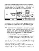
Summary of Contents for OL6FA072D48
Page 2: ......
Page 4: ......
Page 7: ...2...
Page 56: ...51 VIII Sequence of Operations Flow Chart...
Page 57: ...52...
Page 58: ...53 IX Trouble Shooting Flow Chart...
Page 59: ...54...
Page 60: ...55...
Page 61: ...56...
Page 62: ...57...


