4
R70-32 (WEB)
REV(12-04) D
CHANGING THE CHART PAPER
Press and hold the "change chart" button (#3) for
approximately one (1) second until the pen begins to
move to the left of the chart and then release the
button. Wait until the pen has moved completely off of
the chart. To remove the chart paper, unscrew
(counter-clockwise) the chart "hub" knob at the center
of the chart. Remove the old chart paper and position
the new one so that the correct time line coincides
with the time line groove on the chart plate. Refer to
Figure 5 for the location of the time line groove.
Re-attach the chart "hub" knob and screw securely (by
hand) against the chart. Press and hold the "change
chart" button (#3) again for approximately one (1)
second until the pen begins to move back onto the
chart and then release the button. Check to make sure
that the pen is marking on the chart paper. If it is not,
then carefully adjust the pen arm to establish contact
with the paper.
MARKING SYSTEMS:
MARK-A-MATIC II INKING SYSTEM
This type of pen consists of a self contained ink
reservoir with a porous plastic stylus which is snapped
around the outer edge of the metal pen arm.
A pen cap is provided to extend the life of the ink pen
during shipping or when the recording unit is not in
service. To remove the pen cap, gently lift the pen arm
away from the chart paper. Remove the black plastic
pen cap to expose the fiber tip of the ink pen and
gently place the pen back onto the chart paper. Do not
let the pen arm "snap" back onto the chart paper. This
will flatten the fiber tip of the pen and will no longer
give you a fine line marking on the chart paper. Place
the pen cap in a safe place for future use.
If the stylus does not touch the chart, adjustment can
be made by slightly bending the metal pen arm in the
center towards the chart paper. Do not use more
pressure than is necessary to create a fine line marking
on the chart paper.
Note:
As the pen ink supply runs
out, the pen color will become lighter. This indicates
that the pen should be replaced.
REPLACEMENT OF PEN
Note:
In non-inking units, (that is, when using
pressure sensitive recording chart paper) replacement
of the pen is not necessary.
Recorders that are equipped with fiber tipped cartridge
pens will have a cartridge that is color coded "red" to
designate pen number one (1) and an optional
cartridge that is color coded "blue" to designate pen
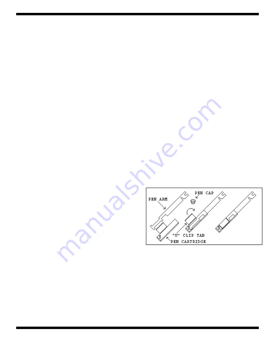
number two (2). The pen cartridge is securely fastened
to the metal pen arm using a special "U" clip tab.
For ease of replacement, it is suggested that the two
(2) screws that hold the pen arm be loosened and the
pen cartridge and metal pen arm be removed as an
assembly. Refer to Figure 5 for the location of the pen
arm screws. Unsnap the plastic "U" clip tab of the pen
cartridge from the metal pen arm, remove and discard
the old pen cartridge. Replace the new cartridge by
opening the hinge and snapping it securely around the
metal pen arm. Refer to the following figure.
Figure 2: Pen Arm Assembly.
PEN ARM CALIBRATION
To check and/or adjust the recording pen(s)
calibration to the outer most temperature graduation
of the chart, press and hold the "change chart" button
(#3) until the pen begins to move off of the chart.
Once the pen(s) has moved off of the chart, again
press and hold the "change chart" button (#3) until the
pen begins to move back onto the chart. The pen
Summary of Contents for 3940 Series
Page 5: ...Thermo Electron Corporation iv Model 3940 Series Thermo Electron Corporation Preface ...
Page 7: ......
Page 19: ......
Page 25: ......
Page 29: ......
Page 47: ......
Page 51: ......
Page 53: ......
Page 54: ...Model 3940 Series 7 1 Thermo Electron Corporation Section 7 Refrigeration Schematics ...
Page 55: ......
Page 56: ...Model 3940 Series 8 1 Thermo Electron Corporation Section 8 Electrical Schematics ...
Page 57: ...8 2 Model 3940 Series Thermo Electron Corporation Section 8 Electrical Schematics ...
Page 58: ...Model 3940 Series 8 3 Thermo Electron Corporation Section 9 Electrical Schematics ...
Page 59: ......
Page 60: ...8 4 Model 3940 Series Thermo Electron Corporation Section 9 Electrical Schematics ...
Page 61: ...Model 3940 Series 8 5 Thermo Electron Corporation Section 9 Electrical Schematics ...
Page 62: ...8 6 Model 3940 Series Thermo Electron Corporation Section 9 Electrical Schematics ...
Page 63: ......
Page 76: ...11 R70 32 WEB REV 12 04 D Figure 7 6 Recorder Case Dimensions ...


