


4
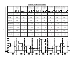
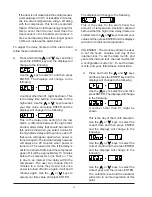
The incubator leaves the factory with a default
schedule as follows:
Hr1
1am
Hr2
1pm
Min1
00
Min2
00
Set1
20.0
Set2
20.0
LGT1 OFF
LGT2 OFF
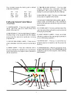
EXPLANATION OF CONTROLS
-Front Panel-
1) AM/PM LAMPS - These two green indicator
lamps inform the user as to what 12-hour time
period of the day it is.
2) TIME DISPLAY - This four-digit display indicates
the time of day. In the program mode, this display
will prompt the user what parameter is being
programmed.
3) DAY-OF-THE-WEEK LAMPS - These seven
green indicators inform the user as to what day it
is.
4) MODE LAMPS - These two indicators inform
the user whether the incubator is in a continuous
mode of operation or a program mode of operation
(timed sequence).
5) TEMPERATURE DISPLAY - This four-digit
display indicates the incubator chamber
temperature. Also, while programming, it will
display the value prompted by the time display.
6) HEATER ON LAMP - This lamp is illuminated
when power is applied to the heater.
7) HIGH/LOW TEMPERATURE ALARM LAMPS -
These lamps will illuminate if the incubator's
chamber temperature exceeds the high or low limit
temperatures.
8) LOCKED LAMP - This lamp will illuminate if the
user has locked the keyboard to avoid accidental
changing of parameters.
9) LIGHT ON/OFF LAMPS - These two lamps
indicate the status of the internal light (whether it
is on or off) during operation.
10) ENTER KEY - This key is used after any
setpoint selection is made to enter the value into
memory.
11) PROGRAM KEY - When the program mode is
selected with the SET key, the PROGRAM key will
prompt the user to enter program values starting
with SUNDAY.
3
4
5
6
7
1
2
8
9
10
11
12
13
14
15
16
18
17
19
Summary of Contents for 3751
Page 5: ......
Page 23: ...18 WIRING DIAGRAMS WIRING DIAGRAM 818 INCUBATOR 120V ...
Page 24: ...19 WIRING DIAGRAM 818 INCUBATOR 230V ...
Page 27: ......
Page 29: ......


