


15
-Measure the voltage at U1-Pin 2 with respect
to TP2. It should be no less than 4 volts DC.
-Measure the DC voltage across R4, since
the incubator is not requesting heat, there
should be no current flowing through this
resistor, making the voltage drop equal to zero
volts.
If the last two steps are not as stated, then
most likely the CPU board is bad and it will
have to be replaced.
-Switch the voltmeter to an "AC Volts" scale
capable of reading 120 volts.
-Measure the voltage between U1-Pin 4 and
U1-Pin 6. It should be line voltage. 110 VAC
to 120 VAC.
If it is not, most likely the Optoisolator is bad
and the power supply board will have to be
replaced.
-Measure the voltage TB1-4 (Orange wire)
and TB1-6 (Red wire). It should be
approximately 0 VAC.
If it is not, then most likely the triac is bad,
and the power supply board will have to be
replaced.
C) This second section will be to verify the heater
command is correct from the microprocessor,
through the optoisolator, and through the Triac
when the incubator is requesting heat. The
steps in this section must be followed in
progression.
-Select a setpoint temperature at least 10°
above what the actual temperature is. The
incubator should be requesting heat as
indicated by the "Heater On" indicator lamp
on the front panel. It should be on
continuously, not flashing.
-Measure the voltage at U1-Pin 2 with respect
to TP2. It should be no greater than 4 volts
DC.
There is another device known as an
Optoisolator which serves as the high/low
voltage isolator between the triac and the
microprocessor.
When the incubator starts experiencing
temperature problems and/or variations, due
to known controller malfunctions, these two
components become prime suspects. The
reason being they are under higher operating
stress than other components.
If the incubator starts experiencing
temperature problems such as no heat,
constant heat, or "creeping" upward heat, then
follow the troubleshooting instructions below.
These instructions require the use of a
voltmeter being able to measure DC and AC
voltages and preferably a digital voltmeter.
WARNING
THE FOLLOWING TROUBLESHOOTING
INSTRUCTIONS REQUIRE THAT POWER BE ON.
ONLY QUALIFIED SERVICE PERSONNEL SHOULD
PERFORM THESE PROCEDURES.
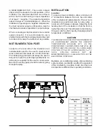
A) Remove the control cover and familiarize
yourself with the power supply assembly
#
3176818
. Locate the Triac (Q2), the
Optoisolator (U1), resistor (R4). Also locate
the test point #2 (TP2). The first
measurements will be DC voltage
measurement, so a DC scale of at least 10
volts should be selected. Connect the
negative lead to TP2. This is DC ground. Also
locate the terminal block (TB1).
B) This first section will be to verify the heater
command is correct from the microprocessor,
through the optoisolator, and through the Triac
when the incubator is NOT requesting heat.
The steps in this section must be followed in
progression.
-Select a setpoint temperature at least 10°
below what the actual temperature is. The
incubator should not be requesting heat as
indicated by the "Heater On" indicator lamp
on the front panel. It should not be on
continuously or even flashing.
Summary of Contents for 3751
Page 5: ......
Page 23: ...18 WIRING DIAGRAMS WIRING DIAGRAM 818 INCUBATOR 120V ...
Page 24: ...19 WIRING DIAGRAM 818 INCUBATOR 230V ...
Page 27: ......
Page 29: ......


