background image

39

14. Tips & Notes

• As already mentioned, the mains unit is in “standby” mode after being switched off by means of

the Power key of the ATX housing.

Therefore, it is not separated from the mains voltage! It works like e.g. a TV set which can be set

to “standby” mode by means of the remote control.

In “standby” mode, the ATX mains unit still draws current. To save energy, switch off the ATX

mains unit by means of the mains switch, if you do not need your computer.

The same is valid for all other devices connected to the computer such as e.g. monitor, scanner,

loudspeakers etc.

Devices without a “real” mains switch (e.g. many computer speakers, some monitors or all

devices with plug mains unit) can be separated from the mains voltage by means of a multiple
socket with an On/Off switch.

â

The standby current consumption of an entire computer system might easily reach 50W.
After only one day, one kilowatt hour (1 kWh) is “wasted” without any use and has been
converted into heat.

Therefore, the purchasing of a multiple socket with On/Off switch will pay off after one year

already.

â

The joint switching on of all loads (computer, monitor, printer etc.) might involve triggering
of the circuit breaker of the respective current circuit, because the switch-on current is
too high.

If this happens, first switch on the switch of the multiple socket and then switch on the individual

devices one after the other.

For switching off, proceed in reverse order: First switch of the devices, then the multiple socket.

There are also so-called “Power Managers” which allow simple switching on/off of individual

sockets via switches on the front. Such “Power Managers” can be placed e.g. under the monitor.

â

Ink jet printers have to be first switched off via the on/off switch of the printer, before the
mains voltage is switched off e.g. by means of the multiple socket.

Otherwise, the printer cannot bring the printing head into the parking position and the
nozzles of the printing head might dry!

Some printers should always be connected to the mains voltage, because otherwise they
would perform an additional cleaning when the mains voltage is applied again (i.e. when
switched on via the multiple socket). The costs of the useless ink consumption are higher
than the energy saving.

• If your mainboard is equipped with a 4-pin ATX2.0 connection for the +12V voltage (e.g. on most

mainboards for Intel-P4 or AMD64 CPU), connect it to the respective connection of the ATX
mains unit (see chapter 13.d).

The connection is intended for better supply of the switching regulators on the mainboard

(generating current or voltage for the CPU) and for relieve of the +12V line of the ATX power
connector. If the connector is not connected, the mainboard might not start.

Summary of Contents for TWV 500W

Page 1: ...urrent technical specifications at time of print We reserve the right to change the technical or physical specifications Copyright 2005 by Conrad Electronic GmbH Printed in Germany Note de l éditeur Cette notice est une publication de la société Conrad Electronic GmbH Klaus Conrad Str 1 92240 Hirschau Allemagne Tous droits réservés y compris traduction Toute reproduction quel que soit le type par ...

Page 2: ...st of contents with the corresponding page numbers can be found in the index on page 23 Cemoded emploiappartientàceproduit Ilcontientdesrecommandationsencequi concerne sa mise en service et sa manutention Veuillez en tenir compte et ceci également lorsque vous remettez le produit à des tiers Conservez ce mode d emploi afin de pouvoir vous documenter en temps utile Vous trouverez le récapitulatif d...

Page 3: ...rzustellen müssen Sie als AnwenderdieseBedienungsanleitungbeachten Alle enthaltenen Firmennamen und Produktbezeichnungen sind Warenzeichen der jeweili gen Inhaber Alle Rechte vorbehalten Bei Fragen wenden Sie sich an unsere Technische Beratung Deutschland Tel 0180 5 31 21 11 Fax 0 96 04 40 88 48 E Mail tkb conrad de Mo bis Fr 8 00 18 00 Uhr Österreich Tel 072 42 20 30 60 Fax 072 42 20 30 66 E Mail...

Page 4: ...schalter 9 c Lüfter 9 d Schraubenlöcher 9 e Anschlüsse für Verbindungskabel 10 f 5 25 Einschub mit Display 10 7 Einbau 11 8 Handhabung 13 9 Wartung und Reinigung 15 10 Entsorgung 15 11 BehebungvonStörungen 16 12 TechnischeDaten 17 13 Anschlussbelegung der Stecker 18 a ATX Stecker 18 b 5 25 Stecker 18 c 3 5 Stecker 18 d 4poligerATX12V Stecker 19 e 6poligerPCIe Stecker 19 f SATA Stromstecker 19 14 T...

Page 5: ...dürfen keinerlei Schrauben oder Befestigungen des Produkts gelöst oder entfernt werden Eine andere Verwendung als zuvor beschrieben führt zu Beschädigungen dieses Produkts außerdem ist dies mit Gefahren wie z B Kurzschluss Brand elektrischer Schlag etc verbunden Beachten Sie alle Sicherheits und Montagehinweise dieser Bedienungsanlei tung 2 Symbol Erklärungen Das Symbol mit dem Blitz im Dreieck wi...

Page 6: ...herheits undZulassungsgründen CE istdaseigenmächtigeUmbauenund oder Verändern des Produkts nicht gestattet Außerdem erlischt dadurch die Garan tie Gewährleistung Das Produkt ist kein Spielzeug es ist nicht für Kinder geeignet Kinder können die Gefahren die im Umgang mit elektrischen Geräten bestehen nicht einschätzen Lassen Sie in Anwesenheit von Kindern besondere Vorsicht walten diese könnten ver...

Page 7: ...f dem Gerät oder in dessen Nähe ab Betreiben Sie das Produkt nur in gemäßigtem Klima nicht in tropischem Klima FassenSieNetzteil Computer NetzkabelundNetzsteckerniemalsmitfeuchtenoder nassen Händen an Gefahr eines lebensgefährlichen elektrischen Schlages Ziehen Sie den Netzstecker nicht am Kabel aus der Netzsteckdose ziehen Sie ihn immernurandendafürvorgesehenenGriffflächenausderNetzsteckdose Glei...

Page 8: ...lten liegt immer noch eine Standby SpannunganIhremMainboardan Diese wird z B benötigt zum Einschalten des Computers über Tastatur oder Maus sofern das BIOS Ihres Computers diese Möglichkeit vorsieht oder das automatische Einschalten HochfahrenbeieinemModem ISDN Anruf Netzwerkzugriff abhängigvon BIOS Hard und Software BeiEingriffeninIhrenComputer z B wennSieeineneueSteckkarteeinbauenwollen muss des...

Page 9: ...ußen Durch den großen 120mm Lüfter ergibt sich nicht nur eine größere Luftmenge sondern auch ein leiserer Betrieb Die Drehzahl des Lüfters kann verändert werden Drehzahlregler im Lieferumfang außerdem steht ein Drehzahlausgang zur Verfügung Verdecken Sie niemals die Lüftungsöffnungen des Netzteils durch den Hitzestau wird das Netzteil und die angeschlossenen Komponenten zerstört d Schraubenlöcher ...

Page 10: ...ss nicht mehr alle unbenutztenKabelzusammenbindenoderimGehäusebefestigen f 5 25 Einschub Der Einschub ist zum Einbau in einen 5 25 Schacht Ihres Computergehäuses vorgesehen Das Display zeigt die abgegebene Leistung an Wie bereits erwähnt ist dies jedoch nur ein Näherungswert Weiterhin befindet sich auf dem Einschub ein Drehzahlregler Dieser dient zur Einstellung der Lüfterdrehzahl für das ATX Netz...

Page 11: ...ndesNetzteils sodasses sich aus dem Computergehäuse herausnehmen lässt Schrauben Sie das neue Netzteil mit 4 Schrauben Zollgewinde Gewindelänge max ca 5mm in Ihrem Computergehäuse fest Der 5 25 Einschub mit dem Drehzahlregler ist in einen freien 5 25 Schacht des Computer gehäuseseinzusetzenundfestzuschrauben Verbinden Sie das Kabel für das TWV Display mit dem entsprechenden Anschluss auf dem Netzt...

Page 12: ...en Dieser ist anders belegt das Mainboard wird dadurch zerstört VerlegenSiedieKabelimComputersauberundgeradlinig achtenSiedarauf daßdieKabelnicht gequetscht oder anderweitig beschädigt werden Schützen Sie die Kabel vor den scharfen Kantenim Computergehäuse AchtenSiedarauf dassdieKabelnichtineinenLüftergelangen Verwenden Sie zur Fixierung der Kabel im Computergehäuse z B Kabelbinder KontrollierenSi...

Page 13: ...uter bei Betrieb niemals ab FassenSienichtmitirgendwelchenGegenständen z B Büroklammern Kugelschrei ber Steck und Stricknadeln usw in die Lüftungsschlitze und Geräteöffnungen Kinder könnten versuchen Gegenstände z B Spielzeug in die Lüftungsschlitze Geräteöffnungen des ATX Netzteils bzw des Computers zu stecken DadurchwirddasATX NetzteilundderComputer indeneseingebautist beschädigt Außerdem besteh...

Page 14: ...sATX Netzteil bzw derComputer indeneseingebautist überlängereZeit nicht benutzt wird z B bei Lagerung so schalten Sie es über den Netzschalter aus und ziehen Sie zusätzlich den Netzstecker des Netzkabels aus der Netzsteckdose Wenn Sie den Computer nur über den Power Taster auf der Front des Computer gehäusesausschalten sobefindetsichderComputerbzw dasNetzteilim Standby Modus ähnlich einem Fernsehe...

Page 15: ...assen Sie dies einem Fachmann bzw einer Fachwerkstatt Durch den Lüfter der im ATX Netzteil eingebaut ist wird im Laufe der Zeit je nach Aufstellungsort des Computers mehr oder weniger Staub eingesaugt der sich im Netzteil und auf den Lüfter schaufeln absetzt Dieser Staub kann von außen mittels einem Staubsauger abgesaugt werden TrennenSiedasATX NetzteilvorhervonderNetzspannung ziehenSiedenNetzstek...

Page 16: ...4poligerATX 12V Stecker Wenn das Festplattenkabel verdreht aufge steckt wird könnte der Computer wegen einem Kurzschlussnichtstarten dasATX Netzteilläuftnichtan Manche Mainboards starten nicht wenn der CPU Lüfter nicht oder zu langsam dreht z B CPU Lüfter mit Temperatursensor oder mit geringer Drehzahl zur Geräuschsenkung Rechner startet beim Ein schalten des Netzteils nicht Beim Einschalten des A...

Page 17: ... auf dem 5 25 Einschub das DisplayzeigtdiemomentanvomNetzteilabgegebeneLeistung Alle Stromanschlusskabel je nach Bedarf an absteckbar Spannungsanschlüsse der mitgelieferten Adapterkabel Anzahl der 5 25 und 3 5 Strom stecker könnte sich bei neueren Versionen des Netzteils evtl ändern 1 24poliger ATX Stecker für Mainboard davon ist ein 4poliges Teil abtrennbar für Mainboards mit 20pol ATX Stromansch...

Page 18: ... orange 5V rot 12V gelb 5V rot 12V gelb 5V rot 5V Standby violett nicht belegt Power OK grau GND Schwarz GND Schwarz GND Schwarz 5V rot GND Schwarz GND Schwarz PS ON grün 5V rot GND Schwarz GND Schwarz 12V blau 3 3V orange 3 3V 3 3V orange b 5 25 Stecker 5V rot GND Schwarz GND Schwarz 12V gelb c 3 5 Stecker 12V gelb GND Schwarz GND Schwarz 5V rot ...

Page 19: ...oliger PCIe Stecker GND Schwarz 12V gelb GND Schwarz 12V gelb GND Schwarz 12V gelb f SATA Stromstecker 12V gelb GND Schwarz 5V rot GND Schwarz 3 3 orange â DadieKontaktleistenimSATA SteckernichtfürhoheStrömegeeignetsind werdendie fünf Anschlusskabel auf mehrere Kontakte aufgeteilt ...

Page 20: ...schalter kann sich deshalb bereits nach einem Jahr bezahlt machen â Das gemeinsame Einschalten aller Verbraucher Computer Monitor Drucker usw führtmöglicherweisedazu dassderSicherungsautomatdeszugehörigenStromkreises auslöst da der Einschaltstrom zu hoch ist Falls dies bei Ihnen auftritt schalten Sie zuerst den Schalter der Steckdosenleiste ein und anschließendnacheinanderdieeinzelnenGeräte Beim A...

Page 21: ...itung des ATX Stromsteckers Wird der Stecker nicht angeschlossen startet u U das Mainboard nicht Achtung Verwenden Sie für den 4poligen Anschluss des Mainboards nicht den vom 24poligen ATX Stromstecker abtrennbaren Teilstecker Dieser ist anders belegt Das Mainboard und auch das Netzteil wird dadurch zerstört Verlust von Garantie Gewährleistung Für Mainboards mit 20poligem ATX Stecker ist der 4poli...

Page 22: ...sited at the manufacturer Wekindlyrequesttheusertofollowtheoperatinginstructionstopreservethisconditionandtoensure safeoperation All company names and product designations contained herein are trademarks of the respective owners All rights reserved For more inquiries contact or consult our technical advisory service Germany Tel no 49 9604 40 88 80 Fax no 49 9604 40 88 48 e mail tkb conrad de Mon t...

Page 23: ...Switch 28 c Fan 28 d Screw Holes 28 e Connections for Connecting Cables 29 f 5 25 Plug in Module with Display 29 7 Installation 30 8 Handling 32 9 MaintenanceandCleaning 34 10 Disposal 34 11 Troubleshooting 35 12 Technical Data 36 13 Pin Assignment of the Connectors 37 a ATXConnector 37 b 5 25 Connector 37 c 3 5 Connector 37 d 4 pin ATX 12V Connector 38 e 6 pin PCIe Connector 38 f SATA Power Conne...

Page 24: ...s of the product must be loosened or removed Anyuseotherthantheonedescribedabovedamagestheproduct Moreover thisinvolvesdangers such as e g short circuit fire electric shock etc Please observe all safety and installation notes contained in this operating manual 2 Symbol Explanation The lightning flash with arrow head inside a triangle is used to alert you to potential personal injury hazards such a...

Page 25: ... conversion and or modification of the product is inadmissible because of safety and approval reasons CE Moreover the guarantee will expire The product is not a toy and therefore not intended for children Children cannot see the dangers arising from the use of electrical devices Beespeciallycarefulifchildrenarearound Theymighttrytoputobjectsintothedevice throughaperturesofthehousing Thereisdangero...

Page 26: ...it computer mains cable and mains plug when your hand are damp or wet Danger of a life threatening electric shock Do not disconnect the mains plug from the mains socket by pulling the cable Always disconnect it from the mains socket by taking it at the provided gripping areas The same is valid for the connection for cold devices Do not bend the cables and do not place objects on them If the mains ...

Page 27: ...mainboard This voltage is necessary e g for switching on the computer via the keyboard or the mouse provided the BIOS of your computer allows this possibility or via the automatic switch onorboot upincaseofamodem ISDNcall networkaccess dependingonBIOS hardwareandsoftware Therefore in case of interventions on your computer e g when installing a new plug in board the ATX mains unit has to be switche...

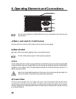
Page 28: ...l apertures B ontherearofthemainsunit Thebig120mmfannotonlyensuresalargeamountofair butalsosilent operation The fan speed can be modified speed regulator is enclosed in delivery Moreover a speed output is provided Nevercovertheventilationaperturesofthemainsunit Duetotheheataccumulation the mains unit and the connected components will be destroyed d Screw Holes The four screw holes E at the outer e...

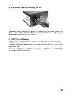
Page 29: ...n use do not have to be bound together or attached inside the housing f 5 25 Plug in Module The plug in module is intended for being installed into a 5 25 slot of your computer housing The display indicates the delivered power As already mentioned above this value only is an approximatevalue Moreover theplug inmoduleisequippedwithaspeedregulator Thisregulatorisintendedforsetting the fan speed for ...

Page 30: ...h approx 5mm Insert the 5 25 plug in module with the speed regulator into a free 5 25 slot of your computer housing and fasten it with screws Connect the cable for the TWV display to the respective connection of the mains unit Via this cable the mains unit sends the value of the present output power to the display Connecttheconnectorofthespeedregulatorofthe5 25 plug inmoduletoasuitableconnection o...

Page 31: ...terneatlyandstraightandmakesurethattheyarenotjammed or otherwise damaged Protect the cables against sharp edges inside the computer housing Make sure the cables cannot get into a fan To secure the cables inside the computer housing use e g cable fasteners Check whether the Power key at the front of the ATX housing is connected to the respective connectiononthemainboard â Switching on via the mains...

Page 32: ...lips biros pins knitting needles etc into the ventilation slots and apertures of the devices Children might try to put objects e g toys into the ventilation slots and apertures of the ATX mains unit or the computer Thus the ATX mains unit and the computer into which it is installed will get damaged Moreover touchingelectriclinesandconnectingpointsinvolveslethaldangerdueto an electric shock Condens...

Page 33: ... longer periodoftime e g incaseofstorage switchitoffviathemainsswitchandadditionally disconnect the mains plug of the mains cable from the mains socket If you switch off the computer only via the Power key at the front of the computer housing the computer or the mains unit are in standby mode similar to a TV set Therefore before any modification of the computer e g when installing a new plug inboa...

Page 34: ...onyourownandletthisbedone by an expert or a specialist workshop In the course of time and depending on the place of installation of the computer the fan integrated into the ATX mains unit might suck in more or less dust that deposits inside the mains unit and on the fan blades This dust can be removed from outside by means of a vacuum cleaner Before doing this separate the ATX mains unit from the ...

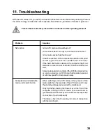
Page 35: ...connector If the hard disk cable is twisted the computer might not startduetoashort circuitandtheATXmainsunitdoesnot start Somemainboardsdonotstart iftheCPUfandoesnotrun or runs too slowly e g CPU fan with temperature sensor or with low speed for decreased noise Computerdoesnotstartwhen mains unit is switched on When switching on the ATX mains unit by means of the mains switch on the rear side of ...

Page 36: ...the 5 25 plug in unit the display indicates the power currently delivered by the mains unit All power supply cables can be connected disconnected as required Voltageconnectionsoftheenclosedadaptercables numberof5 25 and3 5 powerconnectors might change for later versions of the mains unit 1 24 pin ATX connector for mainboard one 4 pin part of the connector can be detached for mainboards with 20 pin...

Page 37: ...3 orange 5V red 12V yellow 5V red 12V yellow 5V red 5V standby purple not assigned Power OK grey GND black GND black GND black 5V red GND black GND black PS ON green 5V red GND black GND black 12V blue 3 3V orange 3 3V 3 3V orange b 5 25 Connector 5V red GND black GND black 12V yellow c 3 5 Connector 12V yellow GND black GND black 5V red ...

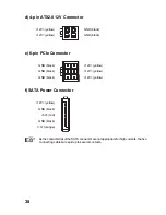
Page 38: ...n PCIe Connector GND black 12V yellow GND black 12V yellow GND black 12V yellow f SATA Power Connector 12V yellow GND black 5V red GND black 3 3 orange â AsthecontactstripsoftheSATAconnectorarenotappropriateforhighcurrents thefive connecting cables are split up to several contacts ...

Page 39: ...n current is toohigh If this happens first switch on the switch of the multiple socket and then switch on the individual devices one after the other For switching off proceed in reverse order First switch of the devices then the multiple socket There are also so called Power Managers which allow simple switching on off of individual socketsviaswitchesonthefront Such PowerManagers canbeplacede g un...

Page 40: ...signeddifferently Thus the mainboard and the mains unit will be destroyed This is not covered by the guarantee Formainboardswith20 pinATXconnector the4 pinpartialconnectorhastobeseparatedfrom the24 pinATXpowerconnector Simplyslideitoff Inthiscase the4 pinpartialconnectorcannot be used for other connections simply let it hang laterally on the cable ...

Page 41: ...ureruneexploitationsansrisques l utilisateurdoit absolument tenir compte de ce mode d emploi et le respecter Tous les noms d entreprises et appellations de produits contenus dans ce mode d emploi sont des marques déposées des propriétaires correspondants Tous droits réservés En cas de questions adressez vous à notre service d assistance technique France Tél 0892 897 777 Fax 0892 896 002 e mail tec...

Page 42: ...rrupteurd alimentation 47 c Ventilateur 47 d Trous de fixation 48 e Connexionspourcâble deraccordement 48 f Rack 5 25 avec écran 48 7 Montage 49 8 Maniement 51 9 Entretienetnettoyage 53 10 Elimination des déchets 53 11 Dépannage 54 12 Caractéristiquestechniques 55 13 Affectation des connecteurs 56 a ConnecteurATX 56 b b Connecteur 5 25 56 c c Connecteur 3 5 56 d Connecteur ATX12V 4broches 57 e Con...

Page 43: ... pas non plus permis de dévisser ou d ôter les vis ou les éléments de fixation Toututilisationautrequecellestipuléeci dessusprovoquel endommagementdeceproduitetest en outre liée à des dangers de courts circuits d incendie d électrocution etc Prenezcomptedetouteslesconsignesdesécuritéetdesconseilsd entretiende ce mode d emploi 2 Explication des symboles Lesymboledefoudreplacédansuntriangleestutilis...

Page 44: ...lire attentivement les points suivants Pour des raisons de sécurité et d homologation CE il est interdit de modifier et ou de transformer cet appareil soi même Ceci annule la validité de la garantie Ceproduitn estpasunjouet maintenez lehorsdelaportéedesenfants Lesenfants nepeuventpasserendrecomptedesdangersprovenantd unmaniementd appareils électriques Maniezl appareilavecvigilanceenprésenced enfan...

Page 45: ...n climat modéré et non pas dans des régions d un climat tropical Netouchezjamaisleblocd alimentation l ordinateur lecâbled alimentationavecdes mains mouillées ou humides ceci pourrait provoquer une décharge électrique dangereuse pour la vie Ne retirez pas la fiche d alimentation de la prise en la tirant par le câble ne la retirez qu en la prenant par les surfaces prévues à cet effet Il en est de m...

Page 46: ...rrêt lacartemère est toujours sous la tension de repos Cette tension est requise par ex pour la mise en service du PC via le clavier ou la souris sous condition que le BIOS de votre PC prévoie cette possibilité ou pour allumer démarrer automatiquement le PC en cas d accès au réseau via modem ISDN dépend du BIOS et du logiciel installé Pour tout changement ou toute transformation de votre ordinateu...

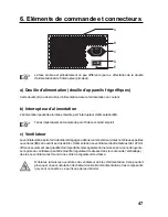
Page 47: ... Ventilateur Leventilateur A aspirel airduboîtieretdégagecedernierversl extérieurvialesnombreusespetites ouvertures B se trouvant au dos du bloc d alimentation Le ventilateur dont la taille est de 120mm offrenonseulementunequantitéd airimportantemaiségalementunemiseenservicenonbruyante Le régime du ventilateur peut être modifié régulateur de vitesse dans le contenu de l emballage de plus le ventil...

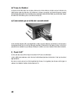
Page 48: ...ion offre la possibilité de n utiliser que les câbles de raccordement nécessaires aux appareils internes Ceci vous offre plus de place à l intérieur de l ordinateur Ainsi vous n avez plus besoin de rattacher ensemble les câbles non utilisés ou de les maintenir fixés dans le boîtier f Rack 5 25 Le rack est prévu pour être intégré à une baie 5 25 de votre ordinateur L écranaffichelapuissancesortie A...

Page 49: ...ncorporés Maintenez fermement le vieux bloc d alimentation et retirez toutes les vieilles vis de fixation de l alimentation de sorte à pouvoir le retirer du boîtier de l ordinateur Fixez la nouvelle alimentation en vissant les quatre vis filet au pouce longueur maximale des vis de 5mm dans le boîtier de votre ordinateur Insérez le rack 5 25 avec le régulateur de vitesse dans une baie 5 25 libre du...

Page 50: ...ée du large connecteur ATX à 24 broches Celle ci est affectée différemment ceci détruirait la carte mère Posez tous les câbles dans le PC de façon exacte et en ligne droite Veillez à ce que les câbles nesoientnicoincésniendommagésdequellemanièrequecesoit Protégezlescâblesdesarêtes vives qui pourraient se trouver dans le boîtier de l ordinateur Veillez à ce que les câbles ne pénètrent pas dans un v...

Page 51: ...ur pendant une mise en service N introduisezjamaisdesobjets parex destrombones desstylosàbille desépingles ou aiguilles etc dans les orifices et fentes d aération de l appareil Les enfants pourraient essayer d introduire des objets par ex des jouets dans les fentes d aération les ouvertures de l alimentation ATX ou de l ordinateur Ceci pourrait endommager l alimentation ATX et l ordinateur dans le...

Page 52: ...l est intégré pour une longue période par ex pendant un stockage débranchez le bloc d alimentation au moyen de l interrupteur principal et retirez en plus la fiche du câble d alimentation de la prise de courant Sivousnedébranchezpasl ordinateuraumoyenduboutonMarche Arrêtsurlapartie avant du boîtier de l ordinateur l ordinateur est alors en mode veilleuse Stanbdy comme pour un téléviseur Avant de m...

Page 53: ...e remplacer le fusible vous même laissez un spécialiste ou un atelier qualifié effectuer le remplacement Auboutd uncertaintempsd utilisationetselonlelieud emplacementdel ordinateur delapoussière finitparsedéposerdansl alimentationATXmontéedansl ordinateuretsurleshélicesduventilateur Cette poussière peut être aspirée de l extérieur au moyen d un aspirateur Séparez l alimentation ATX d abord de la t...

Page 54: ...broches ATX 12V Si par ex le câble du disque dur a été inversé l ordinateur ne pourrait pas démarreràcaused uncourt circuit l alimentationATXne répond pas Quelquescartesmèresnedémarrentpassileventilateur pourunitécentraletourneàunevitessetropbasseoupas dutout parex ventilateurpourunitécentraleavecsonde detempératureouvitessederotationréduitepeubruyant L ordinateurnedémarrepas après avoir allumé l ...

Page 55: ...à l écran à cristaux liquides sur le rack 5 25 l écran affiche la puissance actuelle de l alimentation Tous les câbles de raccordement sont connectables déconnectables selon le besoin Connecteursdetension lenombredesfichesd alimentation5 25 et3 5 pourraitêtredifférent pour les versions ultérieures de l alimentation FicheATX1 24broches pourcartemère dontunmodule4brochesdétachable pourcartes mères à...

Page 56: ...3 orange 5V rouge 12V jaune 5V rouge 12V jaune 5V rouge 5V Standby violet non affecté Power OK gris Tissu noir Tissu noir Tissu noir 5V rouge Tissu noir Tissu noir PS ON vert 5V rouge Tissu noir Tissu noir 12V bleu 3 3 orange 3 3V 3 3 orange b Connecteur 5 25 5V rouge Tissu noir Tissu noir 12V jaune c Connecteur 3 5 12V jaune Tissu noir Tissu noir 5V rouge ...

Page 57: ... noir 12V jaune Tissu noir 12V jaune Tissu noir 12V jaune f Fiche d alimentation SATA 12V jaune Tissu noir 5V rouge Tissu noir 3 3 orange â Comme les réglettes enfichables dans le connecteur SATA ne sont pas appropriées pour des courants élevés les cinq câbles de raccordements sont répartis sur plusieurs contacts ...

Page 58: ... unan l acquisitiond unblocmultiprisesavecinterrupteurd alimentationestcertainement rentable â Lamiseenservicedetouslesappareils ordinateur moniteur imprimanteetc risquede déclencher le coupe circuit automatique du circuit correspondant le courant de fermetureétanttropélevé Si cela était le cas allumez d abord l interrupteur du bloc multiprises et ensuite les différents appareils l un après l autr...

Page 59: ...câble 12V de la fiche d alimentation ATX Si la fiche n est pas connectée la carte mère ne démarre pas Attention N utilisez pas pour la connexion à 4 broches de la carte mère le module détachable de la fiche d alimentation ATX à 24 broches Ce dernier est affecté différemment Ceci détruirait la carte mère de même que l alimentation perte de la garantie PourcartesmèresavecficheATXà20broches lemoduleà...

Page 60: ...treffende verklaringen bevinden zich bij de fabrikant Gelieve deze gebruiksaanwijzing goed op te volgen teneinde deze toestand te behouden en een gebruikzondergevarentewaarborgen Alle firmanamen en productnamen zijn handelsmerken van de respectieve eigenaars Alle rechten voorbehouden Bij vragen kunt u zich wenden tot onze technische helpdesk Nederland Voor meer informatie kunt u kijken op www conr...

Page 61: ... Ventilator 66 d Schroefopeningen 67 e Aansluitingenvoorverbindingskabels 67 f 5 25 insteekeenheidmetdisplay 67 7 Inbouw 68 8 Hantering 70 9 Onderhoudenreiniging 72 10 Verwijderen 72 11 Verhelpenvanstoringen 73 12 Technischegegevens 74 13 Pinbezetting van de connectors 75 a ATX connector 75 b 5 25 connector 75 c 3 5 connector 75 d 4 polige ATX 12V connector 76 e 6 poligePCIeconnector 76 f SATAstro...

Page 62: ...vestigingenvanhetproductlosgemaakt ofverwijderdworden Een ander gebruik dan hier beschreven heeft de beschadiging van het product tot gevolg Dit is bovendien met gevaren verbonden zoals b v kortsluiting brand elektrische schokken enz Gelieve alle veiligheids en montagevoorschriften van deze gebruiksaanwijzing in acht te nemen 2 Uitleg van de symbolen Hetsymboolmetdebliksemineendriehoekwordtgebruik...

Page 63: ...w gezondheid Gelieve de volgende punten aandachtig te lezen Om veiligheids en vergunningsredenen CE is het eigenmachtig ombouwen en of veranderen van het product niet toegestaan Hierdoor zal daarenboven de garantie vervallen Hetproductisgeenspeelgoedenisnietgeschiktvoorkinderen Kinderenkunnende gevaren niet inschatten die ontstaan bij het gebruik van elektrische apparaten Wees bijzonder aandachtig...

Page 64: ... zoals brandende kaarsen op of in de buurt van het productplaatsen Gebruik het product enkel in een gematigd klimaat niet in een tropisch klimaat Umagdevoeding decomputer hetnetsnoerendestekkernooitmetvochtigeofnatte handenaanraken Ditkanlevensgevaarlijkeelektrischeschokkentotgevolghebben Trekdestekkernooitaanhetsnoeruitdecontactdoos maarenkelaandegreepvlakken van de stekker zelf Hetzelfde geldt v...

Page 65: ...panningnaarhetmoederbordgeleverd Deze is b v nodig voor het inschakelen van de computer via het toetsenbord of de muis alsditmogelijkisvolgenshetBIOSvanuwcomputer ofhetautomatischeinschakelen opstartenbijhetaansturenvaneenmodem netwerkofeenISDN oproep afhankelijkvan het BIOS en de hard en software Als u uw computer wilt aanpassen b v als u een nieuwe insteekkaart wilt inbouwen moet daarom eerst de...

Page 66: ... 5 van deze gebruiksaanwijzing c Ventilator Deventilator A trektdeluchtuitdebehuizingenblaastdezedoordevelekleineopeningen B aan de achterkant van de voeding naar buiten Door de grote 120 mm ventilator is de luchthoeveelheid nietenkelgroter maarwerkthetapparaatookstiller Hettoerentalvandeventilatorkanaangepast worden met de meegeleverde toerentalregelaar Er staat bovendien een toerental uitgang te...

Page 67: ...biedtdemogelijkheidomenkeldebenodigdeaansluitkabelsvoordeinterneappparaten tegebruiken Daardoorishetinwendigevandecomputerbetergeordend Dekabelsdienietgebruikt worden moeten niet meer samengebonden of in de behuizing bevestigd worden f 5 25 insteekeenheid De insteekeenheid is geschikt voor de inbouw in een 5 25 bay van uw computerbehuizing Het display toont het afgegeven vermogen aan Zoals reeds v...

Page 68: ...ding met 4 schroeven inch schroefdraad lengte van de schroefdraad max 5 mm in de computerbehuizing vast De 5 25 insteekeenheid met de toerentalregelaar moet in een vrije 5 25 bay van de behuizing geplaatstenvastgeschroefdworden VerbinddekabelvoorhetTWVdisplaymetdebetreffendeaansluitingvandevoeding Viadeze kabel levert de voeding de waarde van het actuele uitgangsvermogen naar het display Verbindde...

Page 69: ...e kabels netjes en rechtlijnig in de computer Let erop dat de kabels niet geplet of op andere wijze beschadigd kunnen raken Bescherm de kabels tegen de scherpe kantjes van de computerbehuizing Let erop dat de kabels niet in een ventilator terecht kunnen komen Gebruik b v kabelbinders om de kabels in de computerbehuizing te fixeren Controleer of de Power toets aan de voorkant van uw ATX behuizing m...

Page 70: ...g de ventilatieopeningen en de computer niet afdekken tijdens het gebruik Steekgeenvoorwerpenzoalsb v paperclips balpennen speldenofbreinaaldene d indeventilatiesleuvenenopeningenvanhetapparaat Kinderenkunnenproberenomvoorwerpen b v speelgoed indeventilatiesleuvenen openingen van de voeding en de computer te steken Hierdoor zullen zowel de voeding als de computer waarin de voeding ingebouwd is bes...

Page 71: ...n u de voeding of de computer met de ingebouwde voeding langere tijd niet gebruikt moetudezemetdenetschakelaaruitschakelenenbijkomenddestekkervan het netsnoer uit de contactdoos halen AlsudecomputerenkelviadePowertoetsaandevoorkantvandecomputerbehuizing uitschakelt bevindendecomputerendevoedingzichinde stand by modus netals bijeentelevisie Als u de computer wilt aanpassen b v een insteekkaart wilt...

Page 72: ...akmanofeenreparatiedienst Door de ventilator die in de voeding ingebouwd is zal er al naar de opstelplaats van de computer mettertijd meer of minder stof aangezogen worden die zich in de voeding of op de ventilatorbladen afzet Dit stof kan met een stofzuiger van buitenaf opgezogen worden Koppel vooraf de voeding los van de netspanning Haal de stekker uit de contactdoos Gebruik voor de reiniging va...

Page 73: ...Xconnector 4 polige ATX 12V connector Als de kabel van de harde schijf verkeerdaangeslotenwerd zaldecomputeromwillevan kortsluiting niet werken en zal de voeding niet opstarten Bepaalde moederborden starten niet als de CPU koeler niet of te langzaam draait b v CPU koelers met temperatuursensor of een laag toerental voor de verminderingvanhetlawaai Decomputerstartnietbijhet inschakelenvandevoeding ...

Page 74: ...displayvande5 25 insteekeenheid het displaytoonthetactueleafgegevenvermogenvandevoeding Allestroomaansluitkabelskunnennaarwensaangesloten losgekoppeldworden Spanningsaansluitingen van de meegeleverde verbindingskabels het aantal 5 25 en 3 5 stroomconnectors kan bij nieuwere versies van de voeding evt afwijken 1 24 polige ATX connector voor het moederbord daarvan kan een 4 polig onderdeel losgekopp...

Page 75: ...3 oranje 5V rood 12V geel 5V rood 12V geel 5V rood 5V stand by paars nietbezet Power OK grijs GND zwart GND zwart GND zwart 5V rood GND zwart GND zwart PS ON groen 5V rood GND zwart GND zwart 12V blauw 3 3V oranje 3 3V 3 3V oranje b 5 25 connector 5V rood GND zwart GND zwart 12V geel c 3 5 connector 12V geel GND zwart GND zwart 5V rood ...

Page 76: ...6 polige PCIe connector GND zwart 12V geel GND zwart 12V geel GND zwart 12V geel f SATA stroomconnector 12V geel GND zwart 5V rood GND zwart 3 3 oranje â DaardecontactpinnenindeSATAstekkernietgeschiktzijnvoorhogestromen worden devijfaansluitdradenovermeerderecontactenverdeeld ...

Page 77: ... kan het gebeurendatdezekeringautomaatvandebijbehorendestroomkringgeactiveerdwordt daar de inschakelstroom te hoog is Als dit bij u het geval is moet u eerst de schakelaar van de stekkerdoos en vervolgens de verschillendeapparatennaelkaarinschakelen Gaopomgekeerdewijzetewerkbijhetuitschakelen eerstdeapparatenendandestekkerdoos uitschakelen Erbestaanookzogeheten powermanagers diehetmogelijkmakenomv...

Page 78: ...aansluitingvanhetmoederbord nietdedeelconnectordievan de24 poligeATXconnectorlosgekoppeldkanworden Dezeheefteenanderebezetting Hierdoor zullen het moederbord en ook de voeding vernield worden en zal de garantie vervallen Voormoederbordenmeteen20 poligeATXconnectorkande4 poligedeelconnectorvande24 polige ATX stroomconnector losgekoppeld worden schuif deze gewoon eruit De 4 polige deelconnector mag ...

Page 79: ...79 ...
Reviews: