TSBC Instruction Manual
Page 11 of 48
Product Features
Energy Management System (EMS) Boiler Control
Display Shows: Outlet Sensor & Remote SP Mode
RJ
11
,
RS
-
485
Communication
Peer
-
To
-
Peer Network
for Modulating Lead
/
Lag
Or
Modbus Network
for Touch Screen or EMS Monitoring
EMS System
Hardwired Connections
Lockout Indicator
(
LO
)
Soft Alarm
(
SO
)
Remote On
/
Off
(
Enable
) (
RO
)
Remote Setpoint
(
C
+
,
C
-
)
Boiler Outlet
Temperature
(
BO
,
BC
)
Boiler Inlet
Temperature
(
BI
,
BC
)
Return
Water
Outside Air
Temperature
(
O
+
,
O
-
)
Boiler
Circulator
System
Circulator
DHW
Override
Switch
(
DP
)
System
Supply Water
Domestic Hot
Water
(
DHW
)
Supply
ALARM
POWER
Outlet Sensor & Remote SP Mode
Application Diagram
(Showing relevant connections)
Features
Setpoints
The setpoint is determined by the Remote Input (C+,C-)
or Modbus Input and operator sets the on and off points
from the LCD display.
Modulation Rate Control
Boiler automatically modulates to maintain the boiler
outlet temperature at setpoint.
Call for Heat
The Call For Heat is determined by setpoint, on and off
points and boiler outlet temperature.
Options
Warm Weather Shutdown (WWSD)
If enabled, the WWSD will disable a boiler start when
temperature is above a Warm Weather Shutdown
(WWSD) setpoint.
Outside Air Temperature may be displayed only.
Outside Air Reset and Domestic Hot Water Priority input
(DP) are ignored.
Selecting This Control Mode
To select Outlet Sensor & Remote SP Mode
set the following
parameters:
System Configuration Menu:
Remote Control = “Remote SP”
Remote System Temperature Sensor = “No”
Local / Remote Input (LR) = Closed
Remote On / Off (Enable) Input (RO) = Closed (Jumper (RO)
to (C) )
When the Local / Remote Input (LR) is open, Remote Input
(C+,C-) is ignored and Outlet Sensor & Local SP Mode is
active.
If the Remote On / Off (Enable) (RO) input is opened, the
Call For Heat Relay (CH) is de-energized.
Modbus Network
To establish a Modbus network set the following parameters:
Communication Menu:
Protocol = Modbus
Modbus Address = Give each boiler a unique address.
Baud Rate = Set identical to remote system.
Parity = Set identical to remote system.
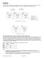
Connect all boilers using a RJ11 ended telephone cable.
If the Modbus network is activated the remote system may
monitor and/or control boiler operation. Refer to page 26 for
additional information.


