background image


Form: 2435-3 

Arctic Installation and Operation Manual 


Revision: 10 

P/N 105641-01 


Date: 12-1-2018 


Thermal Solutions, 1175 Manheim Pike, Lancaster, PA 17601 

Web:


www.

thermalsolutions

.com


Phone: 

717-239-7642 

Fax:

 877-501-5212 

Email:


[email protected] 


38 

5.5


Tube Replacement Procedure 

NOTICE 

Performing  a  regular  boiler  inspection  will  prolong  the  life  of  the  heat  exchanger,  and 
ensure  optimal  function  and  energy  efficiency.  For  best  practices,  adhere  to  the  general 
guidelines outlined in the service and maintenance section of this manual. 

 
1.


Inspect the boiler.  Use the following steps to identify a potential tube leak and to minimize 
possible damage to the boiler and other equipment as a result of tube failures. 
a.


Shut off power to the boiler immediately from the external, dedicated electrical disconnect. 

b.


Confirm that any water leakage is not the result of a blocked condensate drain line. 

c.


Confirm that any water leakage is not the result of a blocked condensate drain line. 

d.


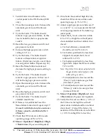
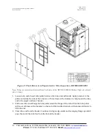
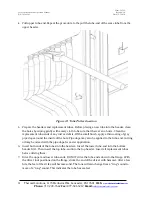
Remove the boiler’s left side jacket panels and flue collector access panels as shown in 
Figure . 

e.


Visually inspect the burner and furnace pass insulation for water damage. If significant water 
damage to the insulation or burner is observed, contact the manufacturer. 

f.


Identify any leaking tubes. 

g.


Isolate and drain the boiler completely. 

2.


Use the proper tools.  Use the following tools to remove and replace leaking boiler tubes: 
a.


Tube Puller (P/N 106019-02) 

b.


Tube Driver (P/N 106019-01) 

c.


Sledgehammer (steel head, approximately 3 lb) 

Summary of Contents for Arctic 1000

Page 1: ...12 Email sales thermalsolutions com i ARCTIC High Efficiency Low Emission CONDENSING BOILER INSTALLATION OPERATION MANUAL For service and repair to the boiler call your heating contractor When seeking information on the boiler from the manufacturer provide boiler model and serial number as shown on the rating label Boiler Model Serial Number Installation Date Type System Heating Contractor Phone E...

Page 2: ...12 3 2 6 2 ARC1500 6000 Condensate Drain Trap 13 3 2 7 Gas Supply Connection 13 3 2 7 1 Drip Leg 13 3 2 7 2 Gas Piping Leak Test 13 3 2 7 3 Venting of Gas Train Components 14 3 3 Combustion Air Supply System 14 3 3 1 Combustion Air Openings 14 3 3 1 1 Two Permanent Opening Method 14 3 3 1 2 One Permanent Opening Method 15 3 3 1 3 Mechanical Air Supply Systems 15 3 3 2 Louvers Grilles and Screens 1...

Page 3: ...itoring 29 4 SYSTEM START UP 30 4 1 Concert Boiler Control Display Navigation This Section applies ONLY to the ARC1000 through ARC3000 30 4 2 System Check 31 4 3 Power the Boiler 31 4 4 Power the Circulators 31 4 5 Pressurize the Fuel System 31 4 6 Boiler Commissioning This Section applies ONLY to the ARC1000 through ARC3000 31 4 7 Finish Commissioning the Boiler This Section applies ONLY to the A...

Page 4: ...3000 115 VAC Single Phase Wiring Diagram 65 Appendix H 3 ARC1500 To ARC3000 208 230 VAC Single Phase Wiring Diagram 67 Appendix H 4 ARC2000 To ARC3000 208 460 VAC Three Phase Wiring Diagram 69 Appendix H 5 ARC3500 To ARC6000 208 460 VAC Three Phase Wiring Diagram 71 Tables Table 1 Water Flow Switch Settings 7 Table 2 Clearances and Serviceability 11 Table 3 Typical Condensate Flow Rate 12 Table 4 ...

Page 5: ... and Components 8 Figure 3 ARC3500 6000 External Boiler Connections and Components 9 Figure4 Clearances and Serviceability 10 Figure5 ARC 1000 Condensate Drain Trap 13 Figure 6 ARC1500 6000 Condensate Drain Trap 13 Figure 7 High Fire Adjustment on the Main Gas Valve Regulator 33 Figure 8 Ignition Assembly 37 Figure 9 Panel Removal in Preparation for Tube Inspection ARC1000 39 Figure 10 Panel Remov...

Page 6: ...n or maintenance which are important but not related to personal injury hazards 1 2 Disclaimers and Local Codes Installation must conform to the requirements of the authority having jurisdiction In the absence of such requirements installation must conform to the National Fuel Gas Code NFPA 54 ANSI Z223 1 and or CAN CGA B149 Installation Codes Where required by the authority having jurisdiction th...

Page 7: ...le contact the fire department 1 4 Component Description 1 Touchscreen display Used on ARC1000 ARC3000 The display provides easy access for viewing and adjusting boiler operational parameters monitoring historical performance characteristics and annunciating boiler alarm lockout conditions 2 Boiler On Off switch Used on ARC1000 ARC3000 3 Manual gas shutoff valve The boiler is equipped with two man...

Page 8: ...er is provided with an internal dip tube that traps liberated air from the boiler water The air vent allows the trapped air to escape from the boiler 13 Boiler reset push button 14 Boiler water temperature gauge 15 Boiler water pressure gauge References 16 to 18 are only used on ARC3500 ARC6000 16 Boiler Hand Off Auto 17 Push Button Display The display provides easy access for viewing and adjustin...

Page 9: ...This boiler must be properly vented WARNING This boiler needs fresh air for safe operation and must be installed so there are provisions for adequate combustion and ventilation air 2 1 Installation Conformance Installation must conform to the requirements of the authority having jurisdiction In the absence of such requirements installation must conform to the National Fuel Gas Code NFPA 54 ANSI Z2...

Page 10: ...y Local codes must be applied to specific installations and the minimum clearances established accordingly Provisions must also be made for service accessibility and clearance for piping and electrical connections Do not obstruct combustion air and ventilation openings with piping or any other construction All boilers must be installed in a space that is large compared to the boiler Figure 4 Clear...

Page 11: ...astic protective cover be left on as long as possible to reduce finish damage from the installation 3 2 Boiler Connections Do not run any pipes along the tube access panel side of the boiler Maintain clearances as shown on the dimensional drawing for servicing of the boiler tubes All piping should be designed and installed to avoid any loadings on the boiler connections or piping 3 2 1 Flow Connec...

Page 12: ... the pH of the condensate should never have a value lower than 3 5 NO VALVE is to be installed in this line from the boiler to point of discharge The condensate drain trap should be flushed with water as part of your boiler maintenance schedule to remove any debris that might have accumulated over time A common condensate pump sump may be used Run separate piping from each condensate drain to the ...

Page 13: ...must conform completely to the requirements of the authority having jurisdiction or in the absence of such requirements shall conform in the U S to the current National Fuel Gas Code ANSI Z223 1 1984 or in Canada to the current Natural gas and propane installation code CAN CSA B149 1 05 and applicable regional regulations for the class which should be followed carefully in all cases Authorities ha...

Page 14: ... outside air THIS MUST BE AVOIDED AT ALL COSTS Provisions should be made to heat the outside combustion air if necessary for personnel comfort Positive means for supplying an ample amount of outside air allowing for the complete combustion of the gas must be provided Movable combustion air dampers automatic or manually adjustable must be electrically interlocked with the boiler to prevent boiler o...

Page 15: ...liances located in the space If exhaust fans are utilized additional air shall be provided to replace the exhausted air Each boiler and other appliance must be interlocked to prevent operation when the mechanical air supply system is not in operation If the combustion air is provided by a buildings mechanical ventilation system the system shall be sized to provide the specified combustion air in a...

Page 16: ...n VI Recommended Rules for Care and Operation of Heating Boilers BOCA National Mechanical Code WARNING Do not locate air intakes where petroleum distillates CFC s detergents volatile vapors or any other chemicals are present Severe boiler corrosion and failure will result 3 3 3 Ducted Combustion Air Ducted combustion air can be connected to the boiler air intake flange Ducts shall be constructed o...

Page 17: ...nsing with regards to the National Fuel Gas Code NFPA 54 ANSI Z223 1 10 Vent pipe system must be fully sealed 11 Atmospheric venting is prohibited 12 Appendix B shall be used to determine the vent system equivalent length 13 It is permissible to run vent pipe through a vertical or horizontal chase provided minimum clearances to combustible materials are maintained 14 The minimum clearance to combu...

Page 18: ...ate drawings in Appendix D of this manual to determine common acceptable configurations of the vent system WARNING Improper venting may result in property damage and the release of flue gasses that contain deadly carbon monoxide CO into the building which can cause severe personal injury and or death WARNING Do not use a barometric damper with this boiler This is a positive pressure system The use...

Page 19: ...ewall venting gas appliance as follow For all side wall horizontally vented gas fueled equipment installed in every dwelling building or structure used in whole or in part for residential purpose including those owned or operated by Commonwealth and where the side wall exhaust vent termination is less than seven 7 feet above finished grade in the area of the venting including but not limited to de...

Page 20: ...ation unless upon inspections the inspector observes carbon monoxide detectors and signage installed in accordance with the provisions of 248 CMR 5 08 2 a 1 through 4 a EXEMPTIONS The following equipment is exempt from 248 CMR 5 08 2 a 1 through 4 i The equipment listed in chapter 10 entitled Equipment Not Required To Be Vented in the most current edition of NFPA 54 as adopted by the Board and ii ...

Page 21: ...ceeding 400 MBH Ventilation Air an opening for ventilation air at the highest point that opens to the outdoors shall provide Ventilation of the space The cross sectional area of this opening shall be at least 10 of the area required for combustion air but in no case shall the cross sectional area be less than 10 in2 6500mm2 Combustion Air For combustion air where the air supply is provided by natu...

Page 22: ...ion Venting for Category IV appliances shall be as specified or furnished by the manufacturer of the listed appliance This boiler is a Category IV appliance requiring the use of special vent that is certified A special venting system shall be installed in accordance with the terms of its listing and the vent manufacturers certified installation manual A flue gas vent or a vent connector shall not ...

Page 23: ...efer to wiring diagram supplied with boiler for wiring information See Appendix H for sample wiring diagrams An as built wiring diagram is included with every boiler when it ships Contact a Thermal Solutions Representative or visit the website www thermalsolutions com for current wiring options 3 5 2 Gas Supply Requirements Refer to Table 6 for minimum and maximum gas supply pressure When the gas ...

Page 24: ...circulating pumps so that the water is pumped away from the boiler is rarely recommended Means to eliminate air from the boiler piping systems is a must It is advised that an air separator be installed as close as practical to each boiler in the outlet pipe Further an air vent should be installed at all high points throughout the piping system It is recommended that a water meter be installed in t...

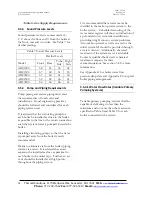
Page 25: ...8 20 20F ARC3000 285 28 7 20F ARC3500 333 11 33 20F ARC4000 380 15 17 20F ARC4500 428 25 17 20F ARC5000 475 33 5 20F ARC5500 523 37 25 20F ARC6000 570 37 92 20F Table 9 Maximum Water Flow Rates for Variable Primary Pumping WARNING Do not use Table 8 or Table 9 to size a constant volume pump 3 5 4 2 Water Flow Rates Primary Secondary Systems Each boiler connected to a secondary loop of a primary se...

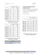
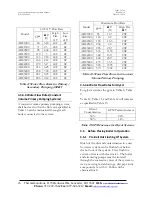
Page 26: ...ected to the system Model Maximum Flow Rate gpm Δ P ft High Fire Δ T ARC1000 95 12 7 20F ARC1500 143 9 2 20F ARC2000 190 16 3 20F ARC2500 238 20 20F ARC3000 285 28 7 20F ARC3500 333 11 33 20F ARC4000 380 15 17 20F ARC4500 428 25 17 20F ARC5000 475 33 5 20F ARC5500 523 37 25 20F ARC6000 570 37 92 20F Table 12 Water Flow Rates for Constant Volume Primary Pumping 3 5 4 4 Water Flow Rates for Glycol F...

Page 27: ... follow the safety precautions on the container s label Add chemicals slowly and in small amounts to prevent excessive heat and agitation The boil out of the boiler and system is neither difficult nor expensive The chemicals needed for cleaning are readily available Tri sodium phosphate and sodium hydroxide lye are the most commonly used chemicals Be certain the chemicals used contain NO CHLORIDES...

Page 28: ...1 Filling The System WARNING Use only clean softened and treated water Chemical treatment of the raw water is essential when filling or refilling the system see section 3 8 3 7 2 Hydrostatic Test Of Boilers And System After completing the boiler and burner installation the boiler connections fittings attachments and adjacent piping must be inspected for leaks by filling the unit with water The pre...

Page 29: ...at the boiler is not operating for long periods without proper water treatment Water treatment may vary from season to season or over a period of time Therefore the water treatment procedure should be checked not less than four times a year and possibly more frequently as the local water conditions may indicate See Table 14 for examples of typical chemical agents found in untreated water along wit...

Page 30: ...ng start up 4 1 Concert Boiler Control Display Navigation This Section applies ONLY to the ARC1000 through ARC3000 This boiler is equipped with a color touch screen display which presents information and control options in a page manner Pages are arranged in a tree structure through which the user navigates up and down to arrive at the desired function The page descriptions and a complete list of ...

Page 31: ...side boiler jacket Confirm that the supply pressure to the manual ball valve tapping outside the boiler jacket conforms to Table 6 for maximum and minimum supply pressure 4 Repeat steps 2 and 3 for boiler gas train components 4 6 Boiler Commissioning This Section applies ONLY to the ARC1000 through ARC3000 All of the installation instructions found in sections 1 through 3 shall be completed before...

Page 32: ...hed reset the flame failure lockout and repeat step 17 Consult with the factory for assistance if flame cannot be established after 3 attempts 19 Check that O2 levels are within a safe operating range 4 5 to 7 0 20 Menu Operation High Low High Back Arrow 76 password required 21 Once boiler has reached high fire rate check that O2 levels are within a safe operating range 4 5 to 7 0 22 Adjust supply...

Page 33: ... C 28 Perform tests on each of the components listed in Table 16 4 7 Finish Commissioning the Boiler This Section applies ONLY to the ARC1000 through ARC3000 Reconnect any wires from the external control system if applicable 1 Perform an operation test of the external control system 2 Place system control back in normal operation if necessary 3 Place the boiler into automatic mode Menu Operation A...

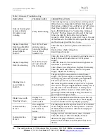
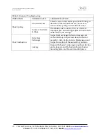
Page 34: ...ntil the switch trips Manually reset the Concert Boiler Control and switch Adjust the switch to its normal setting Hard Lockout Gas Pressure Switch Blocked Condensate Switch Disconnect one wire of the blocked condensate switch Cycle the boiler Re connect wiring to the blocked condensate switch Reset blocked condensate switch lockout Hard Lockout Blocked Condensate Switch Vestibule Thermal Fuse Dis...

Page 35: ...r under high pressure Assure that all gas and electric power supplies are off and that the water temperature is cool before attempting any disassembly or service More than one gas shut off valve and electrical disconnect switch are used on the boiler Assure that all gas valves and electrical disconnect switches are off before attempting any disassembly or service Do not attempt any service work if...

Page 36: ...ns 3 Check operation of probe type low water cutoff s to ensure control is functioning 4 Check gas train for gas leaks and water piping for any leaks 5 Confirm boiler area is free of combustible materials and that there is nothing obstructing air intake and vent 5 1 2 WEEKLY 1 Check combustion safety controls for flame failure or other alarm messages 2 Check all limit controls and low water cutoff...

Page 37: ...ch gap between the igniter and the burner surface Figure 8 Ignition Assembly 1 Igniter 2 Ultra Violet UV Scanner 3 Heat Insulator Igniter Gasket 5 3 Burner Assembly Cleaning 1 After disconnecting power to the boiler remove the boiler s furnace door For part identification refer to the Parts Manual 2 Clean around the burner assembly by blowing compressed air over the surface of the burner to remove...

Page 38: ...the boiler and other equipment as a result of tube failures a Shut off power to the boiler immediately from the external dedicated electrical disconnect b Confirm that any water leakage is not the result of a blocked condensate drain line c Confirm that any water leakage is not the result of a blocked condensate drain line d Remove the boiler s left side jacket panels and flue collector access pan...

Page 39: ...Thermal Solutions 1175 Manheim Pike Lancaster PA 17601 Web www thermalsolutions com Phone 717 239 7642 Fax 877 501 5212 Email sales thermalsolutions com 39 Figure 9 Panel Removal in Preparation for Tube Inspection ARC1000 Figure 10 Panel Removal in Preparation for Tube Inspection ARC1500 ARC3000 ...

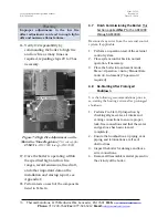
Page 40: ...Right side exploded view not shown 1 Loosen tube ends Insert tube puller between the tube end and header Apply pressure to the puller and strike the side of the tube two or three times with a hammer to help loosen the tube end in the upper and lower header 2 Pull lower tube end Wedge the tube puller under the flange of the tube Drive the tube puller with several blows with a hammer on the end of t...

Page 41: ...lacement tube ends of any rust or debris With a small brush apply a thin coating of gray pipe dope around the inside of the hole Pipe dope may also be applied to the tube end Cutting oil may be mixed with the pipe dope for easier application 6 Insert both ends of the tubes into the headers Insert the lower tube end into the bottom header first Then insert the top tube end into the top header Inser...

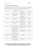
Page 42: ...n 5 6 Safety and Operating Controls All of the safety control devices listed in Table 17 are logically linked to the Concert Boiler Control that supervises the sequence of operation of the boiler for safe and efficient operation It does so by ensuring proper light off and firing of the main burner and if need be will immediately cut off gas supply to the main burner when gas pressure water tempera...

Page 43: ...g Power is interrupted until gas pressure is between the high and low gas pressure set points and the control is manually reset moving the switch to the reset position The switches will not reset until the gas pressure is within the set point parameters Minimum Air Pressure Switch If the differential air pressure drops below the fixed set point the contacts of the switch open and power is interrup...

Page 44: ...tion wiring between boiler J Box and transformer or 24 Vdc power supply Check for loose 24 Vac connection wiring between transformer and Control Check blown low voltage fuse Replace if necessary Check for bad transformer or bad 24 Vdc power supply Replace if necessary Blinking Green power light on Control Control Fault The green light is connected to internal power supply The power supply is repea...

Page 45: ...o determine what adjustments may be made to reduce boiler cycling Contact Manufacturer Incorrect Gas Valve Settings If combustion is too lean or rich as a result of improper gas valve settings adjust air fuel ratio to match factory O2 settings Poor Combustion Dirty Heat Exchanger Inspect heat exchanger tubes for damage and carbon build up Inspect and clean the burner assembly Refer to the Service ...

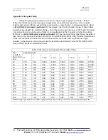
Page 46: ... material other than schedule 40 ipes refer to the National Fuel Gas Code NFPA 54 ANZI Z223 1 and or CAN CGA B149 Installation codes Use methods and materials in accordance with Local Codes and requirements of gas supplier In the absence of such requirement follow National Fuel Gas Codes NFPA ANSI Z 223 1 and or CAN CGA B149 Installation Codes Table 19 Maximum Gas Capacity Of Schedule 40 Pipe Pipe...

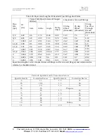
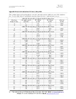
Page 47: ... 824 48 22 9 11 4 5 72 2 06 96 4 12 1 1 049 61 29 1 14 6 7 27 2 62 1 22 5 24 1 1 4 1 38 81 38 3 19 1 9 58 3 45 1 61 6 9 1 1 2 1 61 94 44 7 22 4 11 2 4 02 1 88 8 04 2 2 067 1 21 57 4 28 7 14 4 5 17 2 41 10 3 2 1 2 2 469 1 44 68 5 34 36 17 1 6 16 2 88 12 3 3 3 068 1 79 85 2 42 6 21 3 7 67 3 58 15 3 4 4 026 2 35 112 56 28 10 1 4 7 20 2 6 6 065 3 54 168 84 1 42 1 15 2 7 07 30 4 Equivalent lengths are ...

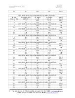
Page 48: ...ssure Drop in Equivalent Feet Flue Vent 8 1 10 5 1728 10 31 3 125 1 56 1106 12 12 1 19 59 768 ARC2500 Pressure Drop in Equivalent Feet Flue Vent 8 1 563 16 67 8 33 2158 10 478 5 2 44 1381 12 183 1 852 92 959 ARC3000 Pressure Drop in Equivalent Feet Flue Vent 8 2 22 25 11 11 2591 10 68 7 14 3 57 1658 12 267 2 7 1 35 1152 ARC3500 Pressure Drop in Equivalent Feet Flue Vent 10 455 4 55 2 727 1935 12 1...

Page 49: ...nt Feet Combustion Air Duct 8 83 8 3 4 17 1576 10 26 2 56 1 28 1009 12 1 98 49 701 ARC3000 Pressure Drop in Equivalent Feet Combustion Air Duct 8 1 19 12 5 5 9 1895 10 37 3 7 1 85 1213 12 14 1 41 7 842 ARC3500 Pressure Drop in Equivalent Feet Combustion Air Duct 10 39 3 92 1 96 1414 12 15 1 49 75 982 14 07 67 33 722 ARC4000 Pressure Drop in Equivalent Feet Combustion Air Duct 10 51 5 13 2 56 1616 ...

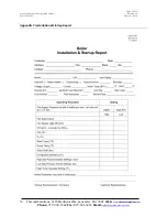
Page 50: ...on Manual Revision 10 P N 105641 01 Date 12 1 2018 Thermal Solutions 1175 Manheim Pike Lancaster PA 17601 Web www thermalsolutions com Phone 717 239 7642 Fax 877 501 5212 Email sales thermalsolutions com 50 Appendix C Installation Startup Report ...

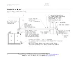
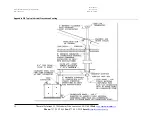
Page 51: ...n 10 P N 105641 01 Date 12 1 2018 Thermal Solutions 1175 Manheim Pike Lancaster PA 17601 Web www thermalsolutions com Phone 717 239 7642 Fax 877 501 5212 Email sales thermalsolutions com 51 Appendix D Venting Diagrams Appendix D 1 Typical Horizontal Vent Piping ...

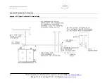
Page 52: ...ual Revision 10 P N 105641 01 Date 12 1 2018 Thermal Solutions 1175 Manheim Pike Lancaster PA 17601 Web www thermalsolutions com Phone 717 239 7642 Fax 877 501 5212 Email sales thermalsolutions com 52 Appendix D 2 Typical Vertical Pressurized Venting ...

Page 53: ... N 105641 01 Date 12 1 2018 Thermal Solutions 1175 Manheim Pike Lancaster PA 17601 Web www thermalsolutions com Phone 717 239 7642 Fax 877 501 5212 Email sales thermalsolutions com 53 Appendix E Combustion Air Diagrams Appendix E 1 Typical Horizontal Air Intake Piping ...

Page 54: ...nual Revision 10 P N 105641 01 Date 12 1 2018 Thermal Solutions 1175 Manheim Pike Lancaster PA 17601 Web www thermalsolutions com Phone 717 239 7642 Fax 877 501 5212 Email sales thermalsolutions com 54 Appendix E 2 Typical Vertical Air Intake Piping ...

Page 55: ...Solutions 1175 Manheim Pike Lancaster PA 17601 Web www thermalsolutions com Phone 717 239 7642 Fax 877 501 5212 Email sales thermalsolutions com 55 Appendix F Boiler Piping Diagrams Typical Layout for all Boiler Models Boilers may look different than pictured Appendix F 1 Single Boiler Primary Secondary ...

Page 56: ...evision 10 P N 105641 01 Date 12 1 2018 Thermal Solutions 1175 Manheim Pike Lancaster PA 17601 Web www thermalsolutions com Phone 717 239 7642 Fax 877 501 5212 Email sales thermalsolutions com 56 Appendix F 2 Multiple Boilers Primary Reverse Return Piping ...

Page 57: ...on 10 P N 105641 01 Date 12 1 2018 Thermal Solutions 1175 Manheim Pike Lancaster PA 17601 Web www thermalsolutions com Phone 717 239 7642 Fax 877 501 5212 Email sales thermalsolutions com 57 Appendix F 3 Multiple Boilers Primary Secondary Reverse Return Piping ...

Page 58: ...l Revision 10 P N 105641 01 Date 12 1 2018 Thermal Solutions 1175 Manheim Pike Lancaster PA 17601 Web www thermalsolutions com Phone 717 239 7642 Fax 877 501 5212 Email sales thermalsolutions com 58 Appendix F 4 Multiple Boilers Primary Secondary Piping ...

Page 59: ...N 105641 01 Date 12 1 2018 Thermal Solutions 1175 Manheim Pike Lancaster PA 17601 Web www thermalsolutions com Phone 717 239 7642 Fax 877 501 5212 Email sales thermalsolutions com 59 Appendix F 5 Multiple Boilers Primary Secondary Piping Heating with Domestic Hot Water ...

Page 60: ...641 01 Date 12 1 2018 Thermal Solutions 1175 Manheim Pike Lancaster PA 17601 Web www thermalsolutions com Phone 717 239 7642 Fax 877 501 5212 Email sales thermalsolutions com 60 Appendix F 6 Multiple Boilers Primary Secondary Piping Heating with Domestic Hot Water continued ...

Page 61: ... 42 2 51 45F 63 1 82 45F 84 3 22 40F 48 3 18 40F 71 2 30 40F 95 4 08 35F 54 4 15 35F 81 3 00 35F 109 5 32 30F 63 5 64 30F 95 4 09 30F 127 7 24 25F 76 8 13 25F 114 5 89 25F 152 10 43 20F 95 12 70 20F 143 9 20 20F 190 16 30 ARCTIC 2500 ARCTIC 3000 ARTIC 3500 Delta T GPM Ft Hd Delta T GPM Ft Hd Delta T GPM Ft Hd 100F 48 0 80 100F 57 1 15 100F 67 42 90F 53 0 99 90F 63 1 42 90F 74 50 80F 59 1 25 80F 71...

Page 62: ... 0 67 70F 136 0 83 60F 127 1 42 60F 143 0 92 60F 158 2 08 50F 152 2 42 50F 171 2 92 50F 190 4 17 45F 169 2 58 45F 190 4 17 45F 211 6 25 40F 190 3 17 40F 214 6 25 40F 238 7 92 35F 217 4 42 35F 244 8 17 35F 271 10 42 30F 253 6 08 30F 285 11 17 30F 317 14 25 25F 304 9 67 25F 342 16 08 25F 380 21 42 20F 380 15 17 20F 428 25 17 20F 475 33 50 ARCTIC 5500 ARCTIC 6000 Delta T GPM Ft Hd Delta T GPM Ft Hd 1...

Page 63: ...vision 10 P N 105641 01 Date 12 1 2018 Thermal Solutions 1175 Manheim Pike Lancaster PA 17601 Web www thermalsolutions com Phone 717 239 7642 Fax 877 501 5212 Email sales thermalsolutions com 63 Appendix H Wiring Diagrams Appendix H 1 ARC1000 Wiring Diagram ...

Page 64: ... 01 Date 12 1 2018 Thermal Solutions 1175 Manheim Pike Lancaster PA 17601 Web www thermalsolutions com Phone 717 239 7642 Fax 877 501 5212 Email sales thermalsolutions com 64 Wiring diagrams are for reference only please refer to the wiring shipped with the boiler for accuracy ...

Page 65: ...ion 10 P N 105641 01 Date 12 1 2018 Thermal Solutions 1175 Manheim Pike Lancaster PA 17601 Web www thermalsolutions com Phone 717 239 7642 Fax 877 501 5212 Email sales thermalsolutions com 65 Appendix H 2 ARC1500 To ARC3000 115 VAC Single Phase Wiring Diagram ...

Page 66: ... 01 Date 12 1 2018 Thermal Solutions 1175 Manheim Pike Lancaster PA 17601 Web www thermalsolutions com Phone 717 239 7642 Fax 877 501 5212 Email sales thermalsolutions com 66 Wiring diagrams are for reference only please refer to the wiring shipped with the boiler for accuracy ...

Page 67: ...n 10 P N 105641 01 Date 12 1 2018 Thermal Solutions 1175 Manheim Pike Lancaster PA 17601 Web www thermalsolutions com Phone 717 239 7642 Fax 877 501 5212 Email sales thermalsolutions com 67 Appendix H 3 ARC1500 To ARC3000 208 230 VAC Single Phase Wiring Diagram ...

Page 68: ... 01 Date 12 1 2018 Thermal Solutions 1175 Manheim Pike Lancaster PA 17601 Web www thermalsolutions com Phone 717 239 7642 Fax 877 501 5212 Email sales thermalsolutions com 68 Wiring diagrams are for reference only please refer to the wiring shipped with the boiler for accuracy ...

Page 69: ...on 10 P N 105641 01 Date 12 1 2018 Thermal Solutions 1175 Manheim Pike Lancaster PA 17601 Web www thermalsolutions com Phone 717 239 7642 Fax 877 501 5212 Email sales thermalsolutions com 69 Appendix H 4 ARC2000 To ARC3000 208 460 VAC Three Phase Wiring Diagram ...

Page 70: ... 01 Date 12 1 2018 Thermal Solutions 1175 Manheim Pike Lancaster PA 17601 Web www thermalsolutions com Phone 717 239 7642 Fax 877 501 5212 Email sales thermalsolutions com 70 Wiring diagrams are for reference only please refer to the wiring shipped with the boiler for accuracy ...

Page 71: ...on 10 P N 105641 01 Date 12 1 2018 Thermal Solutions 1175 Manheim Pike Lancaster PA 17601 Web www thermalsolutions com Phone 717 239 7642 Fax 877 501 5212 Email sales thermalsolutions com 71 Appendix H 5 ARC3500 To ARC6000 208 460 VAC Three Phase Wiring Diagram ...

Page 72: ... 01 Date 12 1 2018 Thermal Solutions 1175 Manheim Pike Lancaster PA 17601 Web www thermalsolutions com Phone 717 239 7642 Fax 877 501 5212 Email sales thermalsolutions com 72 Wiring diagrams are for reference only please refer to the wiring shipped with the boiler for accuracy ...

Page 73: ...en described as thermal shock This warranty does not cover damages or failures that can be attributed to corrosion scale dirt or sludge accumulation in the boiler low water conditions failure of any safety devices or any other improper service operation or neglect FLUE GAS CORROSION WARRANTY Subject to the terms and conditions herein Seller warrants to the original owner at the original installati...

Page 74: ...used by 1 Defective installations in general and specifically any installation which is made a In violation of applicable state or local plumbing housing or building codes b Without a certified ASME pressure relief valve or c Contrary to the written instructions furnished with the unit 2 Adverse local conditions in general and specifically sediment or lime precipitation in the tubes and or headers...

Reviews: