


24
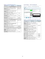
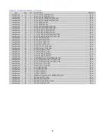
Table 10 – Alarm Setup Parameters
Menu Item
Description
Default Value
High Fluid Temperature
Deviation
This deviation determines the
warning trigger above chiller
setpoint
Supply 10.0°F
Return 50.0°F
Warning
Displays the calculated setpoint
for the warning based on the
deviation setpoint
Fault
Absolute Temperature which the
fault trigger will occur
140
°F
Fault delay
Delay before the alarm will take
action
180 sec.
Fault Action Action takes when high return
fluid alarm occurs
Alarm &
Shutdown
Low Fluid Temperature
Deviation
This deviation determines the
warning trigger below chiller
setpoint
Supply 10.0°F
Warning
Displays the calculated setpoint
for the warning based on the
deviation setpoint
Fault
Absolute Temperature which the
fault trigger will occur
Supply 0.0°F
Evap 38.0°F
Startup
Bypass
Delay time once the system has
started before monitoring High
and Low temperature Alarms.
1200 sec.
Flow Delay
Flow Sensor fault delay timer
5 sec.
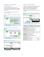
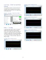
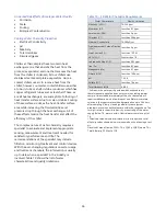
User Setup – Hot Gas Bypass
Figure 46 - User Setup – Hot Gas Bypass Setup
Screen
Table 11 – Hot Gas Bypass Valve Setup Parameters
Menu Item
Description
Default Value
Mode
Selection
AUTO = Follow Automatic Mode
MANUAL = The manual mode
value percent will be the output to
the valve.
AUTO
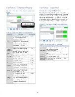
Automatic
Mode
Selection
OFF = The valve will always be
closed (zero output)
LAST ONE = The valve will only
respond relative to the demand
PID when operating with the last
compressor running
ALWAYS = The valve will always
respond relative to the demand
PID regardless of how many
compressors are running.
Last One
Kp
Proportional PID value
0.500
Ti
Integral PID value
300.000
Td
Derivative PID value
0.000
Setpoint
Margin
Temperature deviation below
chiller setpoint to be used for hot
gas bypass control setpoint
0.5°F


