Thermal Arc 175 SE ARC MASTER Operating Manual Download Page 34

ARC MASTER 175 SE                                                                       OpERATION

Manual # 0-5054                                                                       4-8                                                                         March 20, 2008

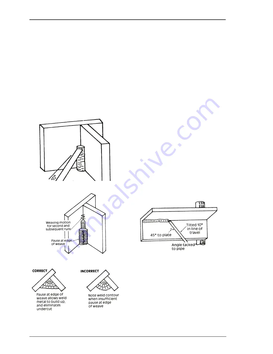
of the fillet. The electrode needs to be about 10° 

from the horizontal to enable a good bead to 

be deposited. Refer Figure 4-16. Use a short 

arc, and do not attempt to weave on the first 

run. When the first run has been completed 

de-slag the weld deposit and begin the second 

run at the bottom. This time a slight weaving 

motion  is  necessary  to  cover  the  first  run 

and obtain good fusion at the edges. At the 

completion of each side motion, pause for a 

moment to allow weld metal to build up at 

the edges, otherwise undercut will form and 

too much metal will accumulate in the centre 

of the weld. Figure 4-17 illustrates multi-run 

technique and Figure 4-18 shows the effects of 

pausing at the edge of weave and of weaving 

too rapidly.

Art # A-07701

Figure 4-16: Single run vertical fillet weld

Art # A-07702

Figure 4-17: Multi run vertical fillet weld

Art # A-07703

Figure 4-18: Examples of vertical fillet welds

2.  Vertical Down
  The E7014 electrode makes welding in this 

position particularly easy. Use a 1/8" (3.2mm) 

electrode at 120 amps. The tip of the electrode 

is held in light contact with the work and the 

speed of downward travel is regulated so that 

the tip of the electrode just keeps ahead of the 

slag. The electrode should point upwards at 

an angle of about 45°.

3.  Overhead Welds
  Apart  from  the  rather  awkward  position 

necessary,  overhead  welding  is  not  much 

more  difficult  that  down  hand  welding.  Set 

up a specimen for overhead welding by first 

tacking a length of angle iron at right angles to 

another piece of angle iron or a length of waste 

pipe. Then tack this to the work bench or hold 

in a vice so that the specimen is positioned in 

the overhead position as shown in the sketch. 

The electrode is held at 45° to the horizontal 

and tilted 10° in the line of travel (Figure 4-

19). The tip of the electrode may be touched 

lightly  on  the  metal,  which  helps  to  give  a 

steady run. A weave technique is not advisable 

for overhead fillet welds. Use a 1/8" (3.2mm) 

E6012 electrode at 120 amps, and deposit the 

first run by simply drawing the electrode along 

at a steady rate. You will notice that the weld 

deposit is rather convex, due to the effect of 

gravity before the metal freezes.

Art # A-07704

Figure 4-19: Overhead fillet weld

4.19  Distortion

Distortion in some degree is present in all forms of 

welding. In many cases it is so small that it is barely 

perceptible, but in other cases allowance has to be 

made before welding commences for the distortion 

that will subsequently occur. The study of distortion is 

so complex that only a brief outline can be attempted 

hear.

Summary of Contents for 175 SE ARC MASTER

Page 1: ...50 60 Hz A 08598 ARC MASTER Inverter Arc Welder 175 SE Operating Manual Revision No AE Issue Date February 24 2009 Manual No 0 5054 Operating Features...

Page 2: ...Precautions They will help you to avoid potential hazards that may exist when working with this product YOU ARE IN GOOD COMPANY The Brand of Choice for Contractors and Fabricators Worldwide ThermalAr...

Page 3: ...hermalarc com Copyright 2008 by Thermadyne Industries Inc All rights reserved Reproduction of this work in whole or in part without written permission of the publisher is prohibited The publisher does...

Page 4: ...Electrical Input Connections 3 1 3 04 Electromagnetic Compatibility 3 3 3 05 Setup for Welding 3 4 3 06 Manual Arc STICK Setup 3 5 3 07 Lift TIG GTAW Setup 3 6 SECTION 4 OPERATION 4 1 4 01 Front Pane...

Page 5: ...01 Routine Maintenance and Inspection 5 1 5 02 STICK Welding Problems 5 2 5 03 TIG Welding Problems 5 3 5 04 Power Source Problems 5 4 5 05 Key Spare Parts 5 4 LIMITED WARRANTY WARRANTY SCHEDULE 2 GLO...

Page 6: ......

Page 7: ...Wear a safety harness to prevent falling if working above floor level 15 Keep all panels and covers securely in place WARNING ARC RAYS can burn eyes and skin NOISE can damage hearing Arc rays from th...

Page 8: ...material 3 Remove all flammables within 35 10 7m of the welding arc If this is not possible tightly cover them with approved covers 4 Be alert that welding sparks and hot materials from welding can ea...

Page 9: ...GINE EXHAUST GASES can kill Engines produce harmful exhaust gases 1 Use equipment outside in open well ventilated areas 2 If used in a closed area vent engine exhaust outside and away from any buildin...

Page 10: ...lowing procedures 1 Keep cables close together by twisting or taping them 2 Arrange cables to one side and away from the operator 3 Do not coil or drape cable around the body 4 Keep welding power sour...

Page 11: ...Welding GMAW Increase Decrease Circuit Breaker AC Auxiliary Power Remote Duty Cycle Percentage Amperage Voltage Hertz cycles sec Frequency Negative Positive Direct Current DC Protective Earth Ground L...

Page 12: ...it t les pi ces endommag es 13 Dans des espaces confin s ou mouill s n utilisez pas de source de courant alternatif moins qu il soit muni d un r ducteur de tension Utilisez plut t une source de couran...

Page 13: ...s l ments peuvent d gager des fum es toxiques au moment du soudage AVERTISSEMENT LE SOUDAGE PEUT CAUSER UN INCENDIE OU UNE EXPLOSION L arc produit des tincellies et des projections Les particules vola...

Page 14: ...cher de tomber ou d tre renver s es 3 Eloignez les bouteilles de tout circuit lectrique ou de tout soudage 4 Emp chez tout contact entre une bouteille et une lectrode de soudage 5 N utilisez que des...

Page 15: ...idi 2 Mettez des gants et posez un torchon sur le bouchon pour l ter 3 Laissez la pression s chapper avant d ter compl tement le bouchon PLOMB AVERTISSEMENT Ce produit contient des produits chimiques...

Page 16: ...Augmentez Diminuer Disjoncteur Source AC Auxiliaire Distant Facteur de Marche Pourcentage Intensit de Courant Tension Hertz cycles sec Fr quence N gatif Positif Courant Continue DC Terre de Protectio...

Page 17: ...equirements Among them are CENELEC EN50199 EMC Product Standard for Arc Welding Equipment ISO IEC 60974 1 BS 638 PT10 EN 60 974 1 EN50192 EN50078 applicable to welding equipment and associated accesso...

Page 18: ...Manual 0 5054 1 12 March 20 2008 ARC MASTER 175 SE SAFETY INSTRUCTIONS...

Page 19: ...h complete information concern ing damage claims or shipping errors to the location in your area listed in the inside back cover of this manual Include all equipment identification numbers as describe...

Page 20: ...x D 230mm Power Source Part Number Welding Output Welding output 40 C 10 min quoted figures refer to SMAW output Dimensions and Weight Dimension power source DxWxH Mains Power Classification Motor st...

Page 21: ...n areas not exposed to direct sunlight or rain Place at a distance of 12 300mm or more from walls or similar that could restrict natural air flow for cooling WARNING Thermal Arc advises that this equi...

Page 22: ...0 National Electrical Code Input Power Each unit incorporates an INRUSH circuit When the MAIN CIRCUIT SWITCH is turned on the inrush circuit provides pre charging for the input capacitors A relay in t...

Page 23: ...erence occurs it may be necessary to take additional precautions such as filtering of the mains supply Consideration should be given to shielding the supply cable of permanently installed welding equi...

Page 24: ...uide only Current delivered to the arc is dependent on the welding arc voltage and as weld ing arc voltage varies between different classes of electrodes welding current at any one setting would vary...

Page 25: ...d Current control to the desired welding current 6 Switch the ON OFF Switch located on the rear panel to the ON position This will immediately energize the power supply up to the output terminals and...

Page 26: ...l to the desired welding current 6 Switch the ON OFF Switch to the ON position 7 Commence welding If necessary readjust the Weld Current control to obtain the welding condition re quired 8 After compl...

Page 27: ...before resuming welding A Process Selection Switch Switches between Lift TIG and Manual Arc STICK Weld ing modes B Power On Indicator The Power ON Indicator illuminates when the ON OFF switch is in t...

Page 28: ...zone in the weld area and if suitable precautions are not taken the occurrence in this zone of under bead cracks Hardened zone and under bead cracks in the weld area may be reduced by using the correc...

Page 29: ...ation Features Colour Code Thoriated 2 DC welding of mild steel stainless steel and copper Excellent arc starting long life high current carrying capacity Red Ceriated 2 AC DC welding of mild steel st...

Page 30: ...ing in flat horizontal vertical and overhead positions Numerous applications call for welds to be made in positions intermediate between these Some of the common types of welds are shown in Figures 4...

Page 31: ...simplest way to commence is to run beads on a piece of scrap plate Use mild steel plate about 1 4 6 0mm thick and a 1 8 3 2mm electrode Clean any paint loose scale or grease off the plate and set it f...

Page 32: ...mes almost automatic You will find that A very long arc produces a crackling or spluttering noise and the weld metal comes across in large irregular blobs The weld bead is flattened and spatter increa...

Page 33: ...hese are welds of approximately triangular cross section made by depositing metal in the corner of two faces meeting at right angles Refer to Figure 4 5 A piece of angle iron is a suitable specimen wi...

Page 34: ...tip of the electrode just keeps ahead of the slag The electrode should point upwards at an angle of about 45 3 Overhead Welds Apart from the rather awkward position necessary overhead welding is not...

Page 35: ...mensions In a welded joint the metal becomes attached to the side of the joint and cannot contract freely Therefore cooling causes the weld metal to flow plastically that is the weld itself has to str...

Page 36: ...pleted the sections b and c will contract at a similar rate thus reducing distortion Art A 07707 Figure 4 22 Principle of presetting Art A 07708 B Preheat Preheat Dotted lines show effect if no prehea...

Page 37: ...essary with solvents that are recommended for cleaning electrical apparatus CAUTION Do not blow air into the power supply during cleaning Blowing air into the unit can cause metal particles to interfe...

Page 38: ...rode angle incorrect rate of travel too high A Small electrodes used on heavy cold plate B Welding current is too low C Wrong electrode angle D Travel speed of electrode is too high E Scale or dirt on...

Page 39: ...ode by grinding contaminates off B Check gas lines for cuts and loose fitting or change gas cylinder 8 Poor weld finish Inadequate shielding gas Increase gas flow or check gas line for problems 9 Arc...

Page 40: ...use Remedy 1 The welding arc cannot be established A The Primary supply voltage has not been switched ON B The Welding Power Source switch is switched OFF C Loose connections internally A Switch ON th...

Page 41: ......

Page 42: ...written consent obtained from Thermadyne service department UK Equipment that has been used beyond the speci cations established in the operating manual Installation not in accordance with the install...

Page 43: ...g District Shanghai PR 200052 Telephone 86 21 69171135 Fax 86 21 69171139 Thermadyne Asia Sdn Bhd Lot 151 Jalan Industri 3 5A Rawang Integrated Industrial Park Jln Batu Arang 48000 Rawang Selangor Dar...

Page 44: ...World Headquarters Thermadyne Holdings Corporation Suite 300 16052 Swingley Ridge Road St Louis MO 63017 Telephone 636 728 3000 Fax 603 728 3010 Email sales thermalarc com www thermalarc com...

Reviews: