SERVICE TROUBLESHOOTING
24
Manual 0-2587
13. Reconnect the ribbon cables to the Upper and
Lower FET/Heatsink Assemblies at J6.
14. If the front panel TEMP indicator is still ON, re-
place the Logic PC Board.
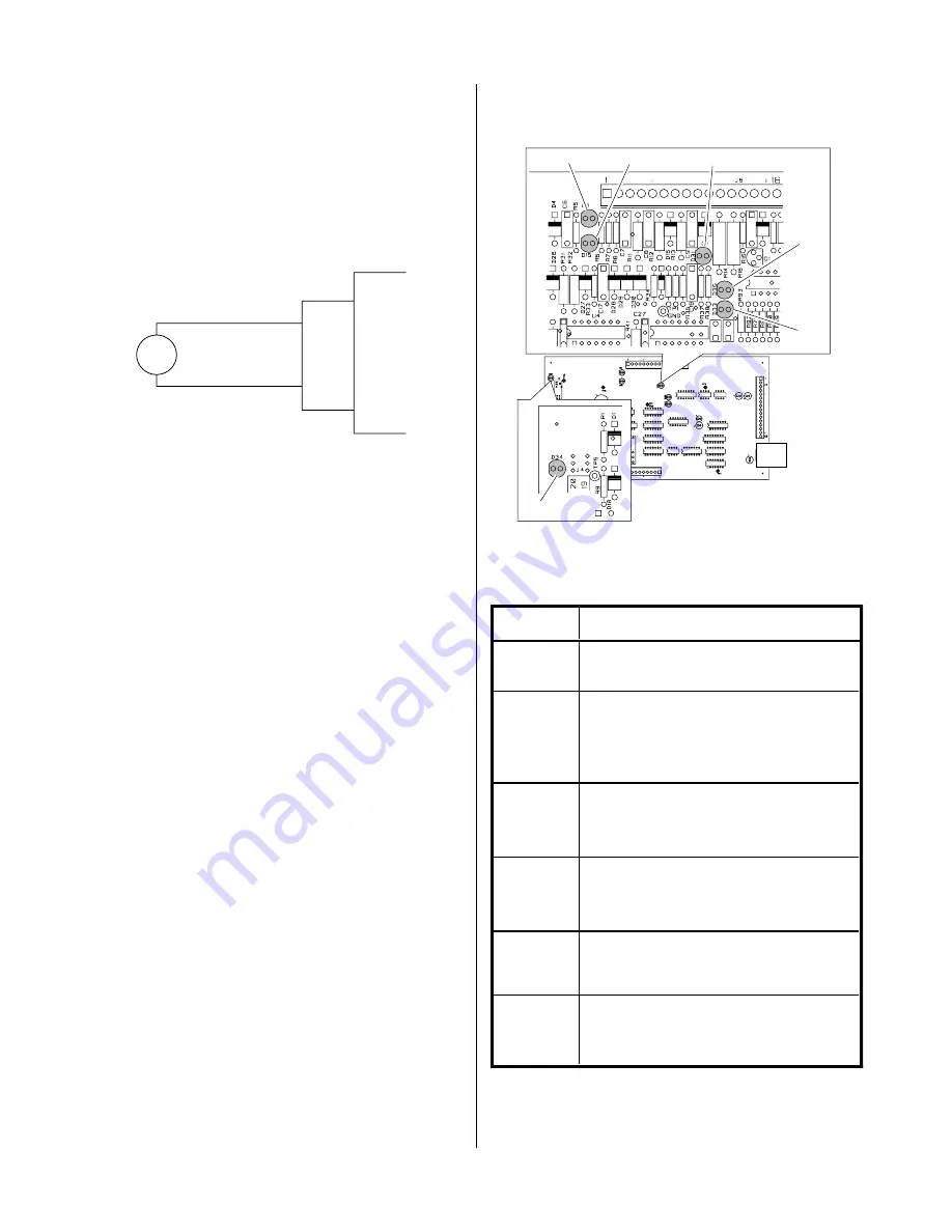
G. Gas Solenoid Circuit Test
Make the following voltage checks per the circuit dia-
gram and replace the faulty part as required.
A-01198
Gas
Solenoid
Wire #56
Wire #52
J2
4
10
Logic PC
Board
1. Check for 115 VAC from Wire #56 to wire #52 at the
gas solenoid.
If approximately 115 VAC replace solenoid.
If no voltage is present proceed to Step 2.
2. Measure for 115 VAC from J2-4 to J2-10 at the Logic
PC Board.
If voltage is not correct replace Logic PC Board.
H. Pilot Arc Circuit
Check across E23 to E24 at the Pilot Output PC Board.
There should be a diode drop across E23 to E24 in one
direction and an open in the other.
If shorted remove the wires at E23 and E24 at the Pi-
lot Output PC Board and check again.
Replace Pilot Output PC Board if shorted from E23 to
E24 (with wires #17 and #16 removed).
I. FET/Heatsink Circuit Tests
The FET/Heatsink circuit tests require various checks to
isolate the possible fault to the FET/Heatsink Assembly.
There are several internal indicators (LED's) on both the
Logic PC Board and the Gate Drive PC Board to help in
troubleshooting.
The indicators on the Logic PC Board as follows:
A-01397
Logic PC
Board
D34
D5
D15
D31
D35
D33
Indicator
Meaning
D5
Torch Switch Enable - When ON
indicates torch switch is pressed.
D15
CD Enable - Initiates spark gap on CD
PC Board. Indicator should come ON
then go OFF after a pilot arc has been
established.
D31
CSR - Indicates main cutting arc is
established.
D33
Pilot ON - Indicates that a true pilot
arc has started. OFF during cutting.
D34
AC OK - When ON indicates that AC
Input voltage is okay.
D35
Drag On - When ON indicates that the
torch tip is making contact with the
workpiece.
Summary of Contents for Thermal Dynamics PAK MASTER 50XL
Page 2: ......
Page 6: ......
Page 16: ...INTRODUCTION 10 Manual 0 2587...
Page 45: ...Manual 0 2587 39 PARTS LISTS A 01381 2 1 3 4 5 2...
Page 47: ...Manual 0 2587 41 PARTS LISTS A 01065 1 2 3 4 5 6 7 8...
Page 49: ...Manual 0 2587 43 PARTS LISTS A 01382 2 4 1 3 5...
Page 53: ...Manual 0 2587 47 PARTS LISTS A 01068 1 6 2 14 12 16 10 15 9 8 7 3 5 5 4 13 17 11...
Page 55: ...Manual 0 2587 49 PARTS LISTS A 01383 14 6 2 11 13 15 7 12 3 8 10 9 4 1 5...
Page 72: ...APPENDIX 66 Manual 0 2587 APPENDIX XII SYSTEM SCHEMATIC A 01370 1 2 1 2...
Page 73: ...Manual 0 2587 67 APPENDIX A 01370 B EC 8055 HAS 11 23 98...
Page 74: ......


